Digital synthesis device for high-speed ultra-narrow pulses

An extremely narrow pulse, digital synthesis technology, applied in the direction of pulse duration/width modulation, single output arrangement, etc., to achieve the effect of strong pulse width controllability, high precision and small pulse width

Inactive Publication Date: 2014-01-01
UNIV OF ELECTRONICS SCI & TECH OF CHINA
View PDF2 Cites 6 Cited by
  • Summary
  • Abstract
  • Description
  • Claims
  • Application Information

AI Technical Summary

Problems solved by technology

However, due to the limitations of device transmission delay and transmission line performance, there is still a lack of modular ultra-narrow pulse synthesis devices with a minimum pulse width of less than 1 ns and pulse width controllability.

Method used


Image

  • Digital synthesis device for high-speed ultra-narrow pulses
  • Digital synthesis device for high-speed ultra-narrow pulses
  • Digital synthesis device for high-speed ultra-narrow pulses

Examples


Embodiment

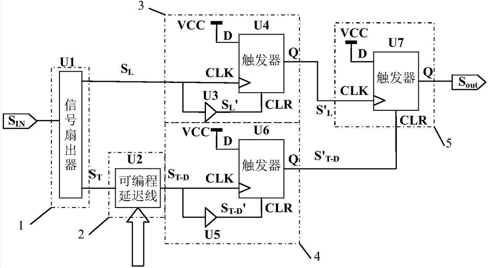
[0025] figure 1 It is the circuit diagram of the high-speed ultra-narrow pulse digital synthesis device of the present invention.

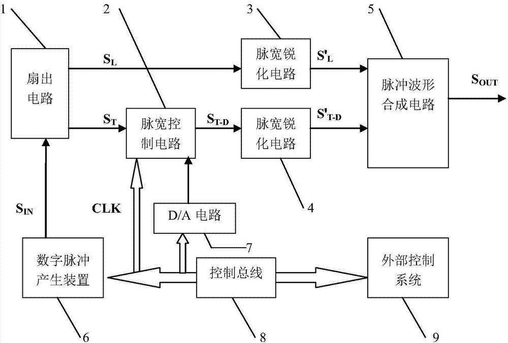
[0026] In this example, if figure 1 As shown, the high-speed ultra-narrow pulse digital synthesis device includes a fan-out circuit 1, a pulse width control circuit 2, a first pulse width sharpening circuit 3, a second pulse width sharpening circuit 4, and a pulse waveform synthesis circuit 5; the fan-out circuit 1 It includes a signal fan-out device U1; the pulse width control circuit 2 includes a programmable delay line U2; the first pulse width sharpening circuit 3 includes a first D flip-flop U4 and a first transmission gate U3; the second pulse width sharpening circuit 4 includes The second D flip-flop U6 and the second transmission gate U5; the pulse waveform synthesis circuit 5 includes a third D flip-flop U7;

[0027] The signal fan-out unit U1 will input the digital pulse signal S IN Fan-out for rising edge signal S L and falling edge...


PUM


Abstract

The invention discloses a digital synthesis device for high-speed ultra-narrow pulses. After digital pulse signals pass through the digital synthesis device for the high-speed ultra-narrow pulses, controllable ultra-narrow pulse signals with the pulse width smaller than 200ps are generated. Due to the fact that the widths of the controllable ultra-narrow pulse signals depend on relative delay between falling edge signals and rising edge signals, synthesis of the ultra-narrow pulses with the adjustable pulse width can be achieved through control over a programmable delay line. Therefore, the whole digital synthesis device for the high-speed ultra-narrow pulses further improves digital synthesis capacity of the minimum pulse width, and has modularization performance of pulse width controllability.

Description

technical field [0001] The invention belongs to the technical field of high-speed pulse generation, and more specifically relates to a high-speed ultra-narrow pulse digital synthesis device. Background technique [0002] Extremely narrow pulse signal is the key factor in the impulse response test of various electronic equipment, and is the basis of high-precision timing technology, time domain reflection technology and time domain transmission technology. It is very important for the testing and development of various radio frequency devices / components and equipment, digital equipment and systems, and has a wide range of applications in various related electronic industries such as aerospace, radar, communications, integrated circuits, and semiconductor characteristic testing. At the same time, in general testing instruments such as high-speed pulse signal generators, high-speed data / pattern generators, time-domain reflectometers, and cable testers, extremely narrow pulse sy...

Claims


Application Information

Patent Timeline
Patent Type & Authority Applications(China)
IPC IPC(8): H03K5/13H03K7/08
Inventor 付在明周文建戴志坚马德坤黄建国田书林
Owner UNIV OF ELECTRONICS SCI & TECH OF CHINA
Why Eureka
Try Eureka