Circuit and method for optical module current subsection compensation

A current segmentation and optical module technology, applied in the field of optical communication, can solve the problems of nonlinear bias current and modulation current, unstable extinction ratio of optical modules, prone to bit errors, etc., and achieve stable optical power and extinction ratio, The effect of not easy to make mistakes and not easy to make mistakes

Active Publication Date: 2014-01-01
WUHAN HENGTAITONG TECH
View PDF4 Cites 2 Cited by
  • Summary
  • Abstract
  • Description
  • Claims
  • Application Information

AI Technical Summary

Problems solved by technology

[0004] At present, the compensation methods for compensating the modulation current of the optical module are generally: temperature look-up table, K coefficient compensation, thermistor, etc. For some optical modules in high temperature environment, the bias current and modulation current of the optical module will have nonlinear characteristics. Therefore, the MCU will have a large deviation through linear compensation, resulting in the instability of the extinction ratio of the optical module. Bit errors are prone to occur during communication

Method used


Image

  • Circuit and method for optical module current subsection compensation
  • Circuit and method for optical module current subsection compensation

Examples


Embodiment Construction

[0028] The present invention will be described in further detail below in conjunction with the accompanying drawings and embodiments.

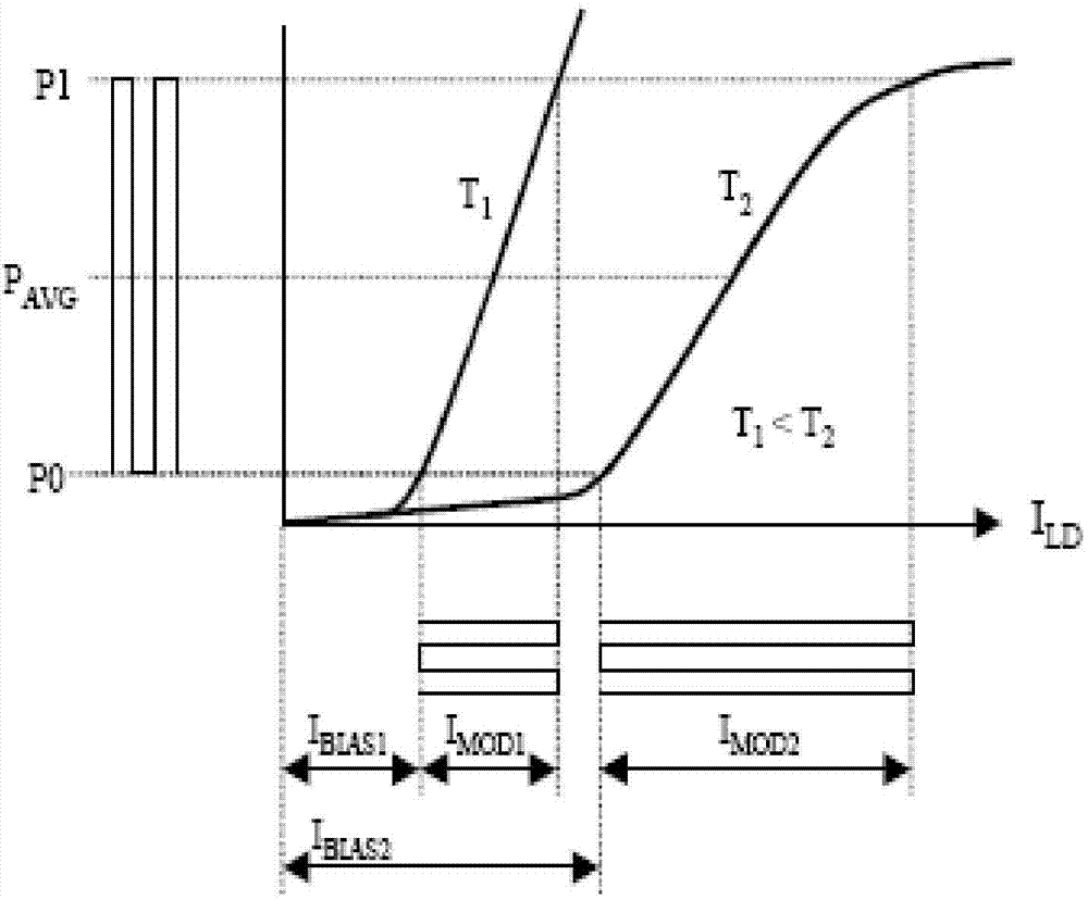
[0029] The circuit and method used for segmental compensation of the optical module current in the embodiment of the present invention are obtained by studying the characteristics of the laser. see figure 1 As shown, in order to understand the temperature characteristics of the laser, a temperature test was performed on the laser, and then the PI (power, current) diagram of the laser was obtained; figure 1 The explanations of the English abbreviations are as follows:

[0030] P1: optical power of the laser when the signal is 1; P0: optical power of the laser when the signal is 0; P AVG : Average optical power, P AVG =(P1+P0) / 2;

[0031] T1: 25°C; I BIAS1 : laser bias current at 25°C; I MOD1 : modulation current of the laser at 25°C;

[0032] T2: 85°C; I BIAS2 : laser bias current at 85°C; I MOD2 : modulation current of the laser at 85...


PUM


Abstract

The invention discloses a circuit and a method for optical module current subsection compensation, and relates to the field of optical communication. The method includes the steps that a third resistor and a working power source are connected, positive bias is generated by the circuit, and a laser is conducted; bias current and modulated current of the laser are absorbed by a second transistor, and the laser is modulated through a damping resistor and a second capacitor; voltage difference of a first resistor is measured, and a bias current value of the laser is calculated; voltage pressure of a second resistor is measured, and a modulated current value of the laser is calculated; the third resistor and the working power source are disconnected, the laser is closed, and the bias current and the modulated current of the laser are measured at measurement temperatures; slope efficiency of the bias current and slope efficiency of the modulated current of the laser are measured within a measurement temperature range. According to the circuit and the method for optical module current subsection compensation, compensation stability and compensation accuracy on an optical module are high, stability and accuracy of the optical module are improved, stability of luminous power and extinction ratio of the optical module can be guaranteed in a full-temperature range, and error codes can not happen easily in the communication process.

Description

technical field [0001] The invention relates to the field of optical communication, in particular to a circuit and method for segmental compensation of optical module current. Background technique [0002] With the rapid development of the optical communication industry, the triple network integration of data communication, IP communication and voice communication is accelerating, and the demand for optical modules is increasing day by day. As the application environment of optical modules becomes more and more complex, traditional APC (Automatic Power Control, automatic power control) optical power compensation and linear extinction ratio compensation cannot guarantee the stability of optical power and extinction ratio of the module in the full temperature range. [0003] When the traditional optical module is used, as the temperature changes, the MCU (micro processing unit) needs to compensate the transmitted optical power and extinction ratio of the optical module to ensu...

Claims


Application Information

Patent Timeline
Patent Type & Authority Applications(China)
IPC IPC(8): H04B10/2507
Inventor 肖海清张品华
Owner WUHAN HENGTAITONG TECH
Why Eureka
Try Eureka