
Image correction method and system of infrared focal plane detector

An infrared focal plane and image correction technology, which is applied in the field of infrared imaging and can solve the problems of continuous and uninterrupted output of images, increased overall power consumption of the system, and impact on image imaging quality.

Active Publication Date: 2014-01-01
HIVINTEK OPTRONICS SUZHOU
View PDF6 Cites 9 Cited by
  • Summary
  • Abstract
  • Description
  • Claims
  • Application Information

AI Technical Summary

Problems solved by technology

[0006] In the prior art, the image correction method using mechanical shutters is simple to implement, but the introduction of mechanical shutters also brings a series of negative effects on the application, including: it will cause a decrease in system stability and reduce the overall power consumption of the system Increase
Most importantly, the image cannot be output continuously without interruption, which has a certain impact on the image quality

Method used


Image

  • Image correction method and system of infrared focal plane detector
  • Image correction method and system of infrared focal plane detector
  • Image correction method and system of infrared focal plane detector

Examples


Embodiment Construction

[0062] Specific embodiments of the present invention will be described in detail below in conjunction with the accompanying drawings. However, the embodiments of the present invention are not limited thereto.

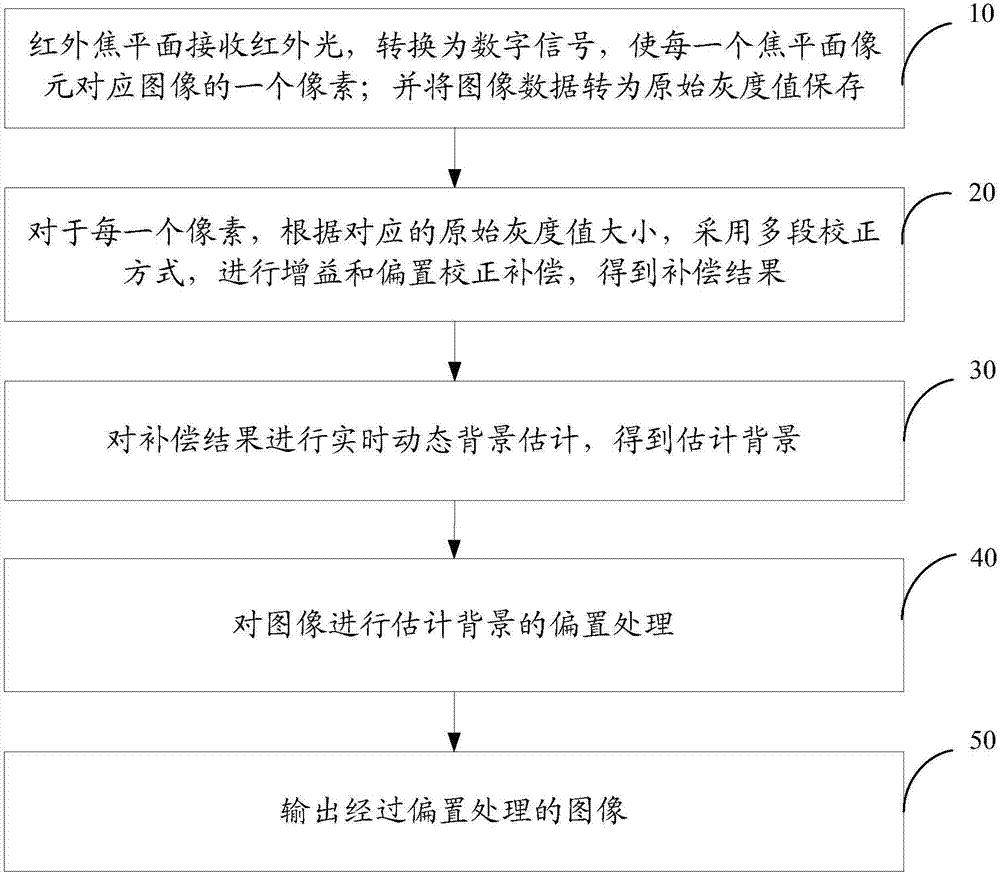
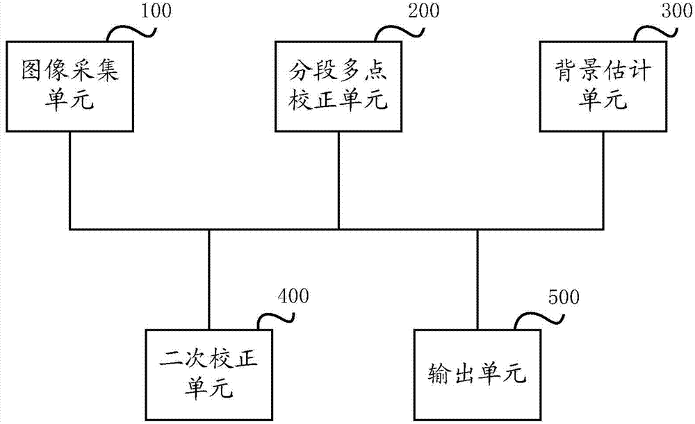
[0063] The principle of each embodiment of the present invention is: to correct the gain and offset of the collected data using the pre-correction coefficient of the corresponding section; to perform real-time background image estimation on the corrected output, and to select pixels that meet the conditions during the estimation process To participate in the operation; use the calculated coefficients to perform secondary image offset correction, and output the final result. By building an infrared image processing system in which no mechanical shutter components are required. The infrared image processing module completes the correction processing of the target infrared signal converted by the infrared light with the focal plane detector, and outputs a stable continuou...


PUM


Abstract

The invention provides an image correction method and system of an infrared focal plane detector. The method comprises the steps that an infrared focal plane receives infrared light and converts the infrared light to a digital signal so as to enable each picture element of the focal plane to correspond to one pixel of an image; image data are converted to original grey values to be stored; for each pixel, gain and offset correction compensation is conducted in a multi-section correction mode according to the corresponding grey values, and a compensation result is obtained. Real-time dynamic background estimation is conducted on the compensation result, and an estimation background is obtained; estimation background offset processing is conducted on the image; an image obtained after offset processing is output. Compared with the prior art, balancing is conducted on calculated performance, image quality and implementation complexity, infrared correction images are continuously output in a blindness-free mode, computation complexity is reduced, the parameter prestorage number is reduced, and power dissipation of the whole system is reduced on the premise that image quality is ensured.

Description

technical field [0001] The invention relates to the technical field of infrared imaging, in particular to an image correction method and system for an infrared focal plane detector. Background technique [0002] At present, the infrared focal plane detector technology is becoming more and more mature, and it is widely used in public security, fire protection, military and other fields. Infrared focal plane detectors have inconsistencies in the response of each pixel during the imaging process. With time and environmental temperature changes, the non-uniformity characteristics are obvious, and the image output quality is unstable. Image correction is required to provide stable imaging quality. [0003] In the prior art, traditional correction methods can be divided into two types. One is scene-based adaptive image correction technology. Scene-based image correction technology can continuously output imaging images without interruption, but there are special restrictions on ...

Claims


Application Information

Patent Timeline
IPC IPC(8): H04N5/33G06T5/00
Inventor 范少华
Owner HIVINTEK OPTRONICS SUZHOU
Learn More