
Multifunctional milk foam cup

A multi-functional, milk foaming technology, applied in the field of cups, can solve the problems of cumbersome operation, difficult to take out and clean, complex structure, etc., and achieve the effects of sensitive and reliable control, safe use and simplified structure

Active Publication Date: 2014-01-08
NINGBO RAVO IND GRP CO LTD
View PDF10 Cites 11 Cited by
  • Summary
  • Abstract
  • Description
  • Claims
  • Application Information

AI Technical Summary

Problems solved by technology

[0002] With the progress of society and the acceleration of the pace of life, various heating, stirring, and milk foaming cups are emerging. The milk foaming cups currently on the market have the functions of heating, stirring, and foaming at the same time, but the milk foaming cups are inconvenient to take out. The surface temperature of the bubble cup dissipates heat quickly and it will be hot to the hands. The structure is complex and difficult to take out and clean, and the milk is inconvenient to pour out.
[0003] CN202681713U proposes a milk frothing cup, in which a motor connected to the stirrer is arranged at the bottom of the cup, and a heater is arranged on the periphery of the motor at the bottom of the cup, and a cup cover is provided outside the cup to prevent scalding, but there are still cumbersome operations, and the milk enters and exits. defects such as inconvenience

Method used


Image

  • Multifunctional milk foam cup
  • Multifunctional milk foam cup
  • Multifunctional milk foam cup

Examples


Embodiment Construction

[0019] Embodiments of the present invention will be further described in detail in conjunction with the accompanying drawings.

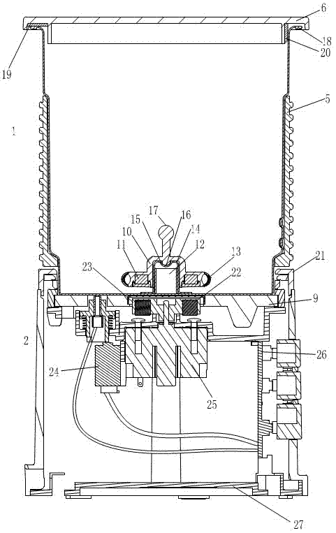
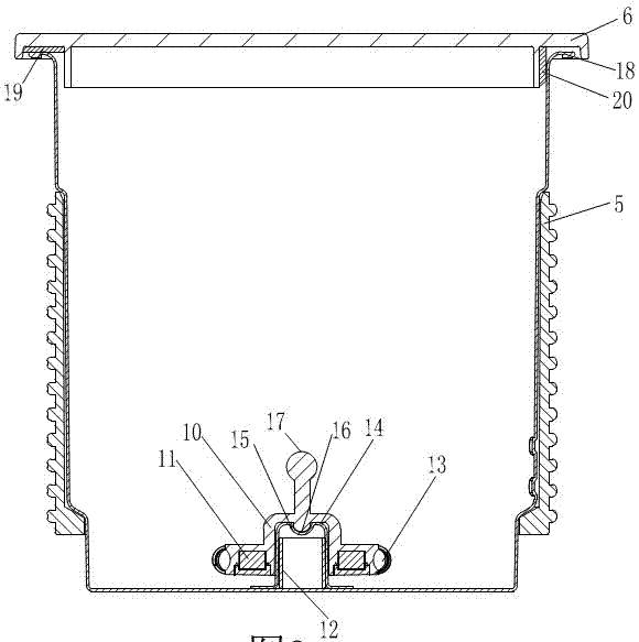
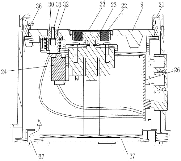
[0020] see figure 1 As shown in FIG. 2 , the milk foam cup includes a cup body 1 and a base 2 , the cup body 1 is provided with a stirring assembly, and the base 2 is provided with an electric assembly and a temperature control assembly. The stirring assembly consists of a boss 14 arranged in the cup body 1, a rotating body 10 resting on the boss 14, stirring permanent magnets 11 on both sides of the rotating body 10, an armature 12 arranged in the boss 14 and a stirring Stirring circle 13 outside permanent magnet 11 forms. A cylindrical boss 14 is arranged in the middle of the cup body 1, and the center of the top surface of the boss 14 is provided with a concave circular hole 15, and the downwardly convex semi-spherical surface 16 in the middle of the rotating body 10 is rotatably fitted with the concave circular hole 15, The outer cylindrical su...


PUM


Abstract

Provided is a multifunctional milk foam cup. The multifunctional milk foam cup comprises a cup body, a base, a stirring assembly, a thermal insulation and heat dissipation piece, an electric assembly and a temperature control assembly, wherein the stirring assembly is arranged inside the cup body, the thermal insulation and heat dissipation piece is arranged outside the cup body, and the electric assembly and the temperature control assembly are arranged inside the base. The stirring assembly is composed of a boss arranged inside the cup body, stirring permanent magnets placed on the two sides of a rotor on the boss, an armature arranged inside the boss and stirring rings arranged outside the stirring permanent magnets. The electric assembly is composed of a motor, a rotor and rotor permanent magnets, wherein the motor and the rotor are arranged inside the base, and the rotor permanent magnets are arranged at the two ends of the rotor. The stirring assembly is isolated from the electric assembly in a rotary seal mode through the bottom face of the cup body, the cup body and the base are sleeved randomly and can be separated at will in position, mutual sleeving at any angle can be achieved as long as the lower portion of the cup body is directed at the recessed circular ring plane of the base, the cup body is stirred, the foaming structure is simplified, and a stirrer is easy to place and convenient to clean. The base is used for temperature sensing and heating control in a sensitive and reliable manner, energy consumption is little, noise is low, using is safe, and environmental protection and practicability are achieved.

Description

technical field [0001] The invention relates to a cup, in particular to a milk foam cup with heating, heat preservation, stirring and foaming functions. Background technique [0002] With the progress of society and the acceleration of the pace of life, various heating, stirring, and milk foaming cups are emerging. The milk foaming cups currently on the market have the functions of heating, stirring, and foaming at the same time, but the milk foaming cups are inconvenient to take out. The surface temperature of the bubble cup dissipates quickly and it will be hot to the hands. The structure is complicated and difficult to take out and clean, and the milk is inconvenient to pour out. [0003] CN202681713U proposes a milk frothing cup, in which a motor connected to the stirrer is arranged at the bottom of the cup, and a heater is arranged on the periphery of the motor at the bottom of the cup, and a cup cover is provided outside the cup to prevent scalding, but there are still...

Claims


Application Information

Patent Timeline
IPC IPC(8): A47J43/046A47J43/07
CPCA47J43/0465
Inventor 陈子均符兴锋商加瑞胡如国
Owner NINGBO RAVO IND GRP CO LTD
Learn More