Novel combined guide float valve tray
A float valve tray and tray technology, which is applied in the field of new combined guide float valve tray, can solve the problems affecting the operation performance of the solid valve tray, restricting the opening height of the valve plate, and small side gap area of the solid valve, etc. The effect of eliminating the non-activation zone, increasing the operating performance and improving the efficiency of the tray
- Summary
- Abstract
- Description
- Claims
- Application Information
AI Technical Summary
Problems solved by technology
Method used
Image

Examples
Embodiment 1
[0089] see Figure 7 , when the liquid flow intensity on the tray (that is, the liquid flow rate per meter of weir length) L3 / m.h, the layout of the new combined guide valve tray is as follows Figure 7 shown. The liquid on the upper tray flows into the opening area of the tray 1 through the liquid tray 10, and the gas flowing out from the rectangular guide valve 2, the trapezoidal guide valve 3 and the first guide valve 4, and the gas on the tray 1. The liquid contacts, then the gas rises, and the liquid flows to the lower tray through the downcomer 13. In the figure, the rectangular guide float valve 2 is as Figure 3a , 3b As shown, the length of the rectangular guide float valve is 80mm, and the lengths of the upstream edge 211 of the bonnet and the downstream edge 212 of the bonnet are 35mm; the trapezoidal guide float valve 3 is as Figure 4a , 4b As shown, the length of the trapezoidal guide float valve is 80 mm, the length of the upstream side 311 of the valve ...
Embodiment 2
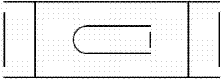
[0091] see Figure 8 , when the liquid flow intensity on the tray L=30~60m 3 / m.h, the layout of the new combined guide valve tray is as follows Figure 8 As shown, the structural type and main dimensions of the rectangular pilot float valve 2 and the trapezoidal pilot float valve 3 are the same as those of the above-mentioned embodiment 1. Figure 8The first guide solid valve 4 in the structure features as shown in Figure 5, the valve plate 41 is directly punched out from the tray 1, forming a valve hole 44 and a side gap 45, and the length range of the valve hole 44 along the liquid flow direction is 50-120mm, the width range is 25-35mm, the opening height range of the valve plate 41 is 8-14mm, on the horizontal section of the valve plate 41, there is an arch bridge type small fixed valve 7, and its fixed valve hole 71 The length along the liquid flow direction ranges from 20 to 40 mm, and the width ranges from 8 to 16 mm. At the front end of the first guide solid valve 4...
Embodiment 3
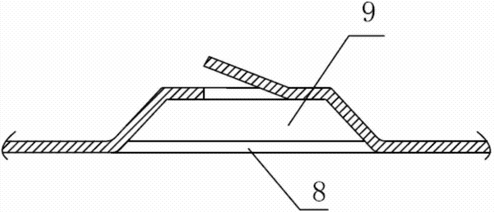
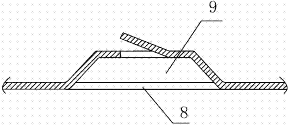
[0094] Please refer to Figure 9, when the liquid flow intensity on the tray increases further, L>60m 3 / m.h, the layout of the new combined guide valve tray is as follows Figure 9 shown. The rectangular guide float valve 2 and the trapezoidal guide float valve 3 in the figure have the same structural type and main dimensions as those of the above-mentioned embodiment 1. Due to the high flow intensity of this example, in addition to the first guide valve 4, a second guide valve 5 with a relatively large thrust is also used. The structural characteristics of the second guide valve 6 are as follows Figure 6a , 6b As shown, the valve plate 51 is directly punched out from the tray 1 to form a valve hole 54 and a side gap 55. The length of the valve hole 54 along the liquid flow direction ranges from 50 to 120 mm, and the length of the upstream edge 52 of the valve plate is in the range of 30-40mm, the length of the downstream edge 53 of the valve plate is 20-30mm. The opening...
PUM
| Property | Measurement | Unit |
|---|---|---|
| Length | aaaaa | aaaaa |
| Length | aaaaa | aaaaa |
| Length | aaaaa | aaaaa |
Abstract
Description
Claims
Application Information
 - R&D
- Intellectual Property
- Life Sciences
- Materials
- Tech Scout
- Unparalleled Data Quality
- Higher Quality Content
- 60% Fewer Hallucinations
Browse by: Latest US Patents, China's latest patents, Technical Efficacy Thesaurus, Application Domain, Technology Topic, Popular Technical Reports.
© 2025 PatSnap. All rights reserved.Legal|Privacy policy|Modern Slavery Act Transparency Statement|Sitemap|About US| Contact US: help@patsnap.com