Oil slinger fan blade for oil fume purifier and manufacturing method thereof

An oil fume purifier and a manufacturing method technology, which are applied in chemical instruments and methods, oil fume removal, separation methods, etc., can solve the problems of reducing the purification rate of the purifier, low purification efficiency, and large wind resistance, so as to reduce wind resistance and purification efficiency. high effect

Active Publication Date: 2015-09-30
佛山市科思博科技有限公司
View PDF5 Cites 0 Cited by
  • Summary
  • Abstract
  • Description
  • Claims
  • Application Information

AI Technical Summary

Problems solved by technology

This is because the front and two sides of the spokes of the dynamic physical shielding purifier of this structure are planes, and when the front is a plane, its wind resistance is large, which reduces the purification rate of the purifier; When the purifier rotates at high speed, the side will generate pressure on the exhaust gas coming in from the front direction. Under the action of the side, the exhaust gas will flow with the direction of rotation of the purifier, and the particles in the exhaust gas will have less chance of contacting the spokes, so the purification rate Low
[0005] Therefore, no matter what kind of structure the interceptor purifier used on the dust removal, oil removal and air purification device adopts, its purification efficiency is low and the purification effect is not ideal.

Method used


Image

  • Oil slinger fan blade for oil fume purifier and manufacturing method thereof
  • Oil slinger fan blade for oil fume purifier and manufacturing method thereof
  • Oil slinger fan blade for oil fume purifier and manufacturing method thereof

Examples


Embodiment 1

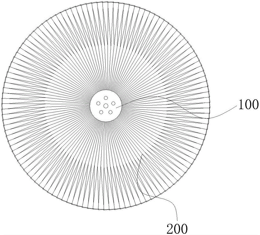
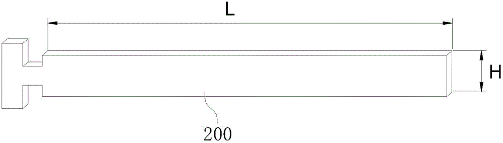
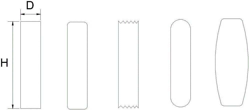
[0065] Such as Figure 1 to Figure 4 Shown is the first embodiment of the present invention used for the oil-fleeing fan blade of the oil fume purifier, as figure 1 As shown, it includes a central disk 100 and several elongated flat blades 200 radially distributed around the central disk 100. One end of these blades 200 is fixedly connected to the central disk 100, and the blades 200 are fixedly connected to the center disk 100. One end is defined as a fixed end, and the other end is defined as a free end. The ratio of the projected area of ​​these blades 200 along the axis of the central disk 100 to the area formed by several blades 200 for blocking oil fume when the oil flinger blade rotates is K1,70 %≤K1≤100%. Wherein, these vanes 200 are flat, that is, the ratio S2 of the height H of the cross section perpendicular to the length direction of the vanes 200 to the thickness D of the vanes 200 is greater than 1. In this embodiment, S2≥1.5, and the height H is calculated. Th...

Embodiment 2

[0076] Such as Figure 5 Shown is the second embodiment of the dynamic physical interception purifier of the present invention, which is used to be installed on the rotating shaft to intercept and separate grease and / or solid particles in the oil fume, such as Figure 5 As shown, it includes a central disk 100 and several elongated flat blades 200 distributed radially or divergently around the central disk 100. One end of these blades 200 is fixedly connected to the central disk 100, and the blades 200 are fixedly connected to the center. One end of the disk 100 is defined as a fixed end, and the other end is defined as a free end. The value of the product of the thickness D of the blade 200 and the number n of blades 200 is S1, 10≤S1≤600, and the unit of the thickness D is millimeters during calculation. n is a natural number, and D≥0.2mm. Wherein, these vanes 200 are flat, that is, the ratio S2 of the height H of the cross section perpendicular to the length direction of th...

Embodiment 3

[0100] Such as Figure 6 to Figure 7 Shown is the third embodiment of the present invention for the oil throwing fan blade of the oil fume purifier, as Figure 6 As shown, it includes a central disk 100 and several elongated flat blades 200 radially distributed around the central disk 100. One end of these blades 200 is fixedly connected to the central disk 100, and the blades 200 are fixedly connected to the center disk 100. One end is defined as the fixed end 210, and the other end is defined as the free end 220. The ratio of the projected area of ​​these blades 200 along the axial direction of the central disk 100 to the area formed by several blades 200 for blocking the oil fume when the oil flinger blade rotates is K1 , 70%≤K1≤100%. Wherein, these vanes 200 are flat, that is, the ratio S2 of the height H of the cross section perpendicular to the length direction of the vanes 200 to the thickness D of the vanes 200 is greater than 1. In this embodiment, S2≥1.5, and the he...


PUM

PropertyMeasurementUnit
diameteraaaaaaaaaa

Abstract

The present invention relates to the technical field of air purification devices such as dust removal and oil removal, and more specifically, to an oil throwing wind blade used for a lampblack purifier and a manufacturing method thereof. A plurality of elongated flat blades distributed radially, one end of the blades is fixedly connected to the central disk, one end of the blades fixedly connected to the central disk is defined as a fixed end, and the other end is defined as a free end. The oil throwing fan blade of the present invention adopts a strip-shaped blade with a sheet structure to replace the existing steel wire structure. When the oil throwing fan blade of the oil fume purifier is working and rotating, the blade forms a wind guide during the rotation process. The contact area of ​​the blades of the structure is large, and the interception surface of the oil fume passing through the oil-sweeping fan blade is increased, that is, the interception rate of the oil fume and other airflows is improved, thereby improving the purification efficiency of the oil-sweeping fan blades on the oil fume and other airflows, and its purification The effect is ideal.

Description

technical field [0001] The invention relates to the technical field of air purification devices such as dust removal and oil removal, and more specifically, to an oil throwing fan blade for a fume purifier and a manufacturing method thereof. Background technique [0002] In recent years, people's living standards have been continuously improved, and people's awareness of health and environmental protection has been increasing. People are eager to have a healthy, clean and environmentally friendly home kitchen environment. At the same time, the catering industry is also booming, and it has played an active role in prospering the economy and improving material living standards. However, the fumes from home kitchens and catering hotels are increasingly polluting the living environment of surrounding residents. In the prior art, there are mainly two structures currently used as an intercepting purifier on a dust removal and air purification device. [0003] The first structure...

Claims


Application Information

Patent Timeline
Patent Type & Authority Patents(China)
IPC IPC(8): B01D45/14F24C15/20
Inventor 谢柳扬
Owner 佛山市科思博科技有限公司
Why Eureka
Try Eureka