

Modified structure of welding pipe squeezing roller seat
A technology of extrusion mechanism and roller seat, applied in the field of steel pipe processing, can solve the problems of insufficient roundness of steel pipe, increase production cost, reduce work efficiency, etc., and achieve the effect of good correction effect, improving work efficiency and reducing processing cost.
- Summary
- Abstract
- Description
- Claims
- Application Information
AI Technical Summary
Problems solved by technology
Method used
Image

Examples
Embodiment 1
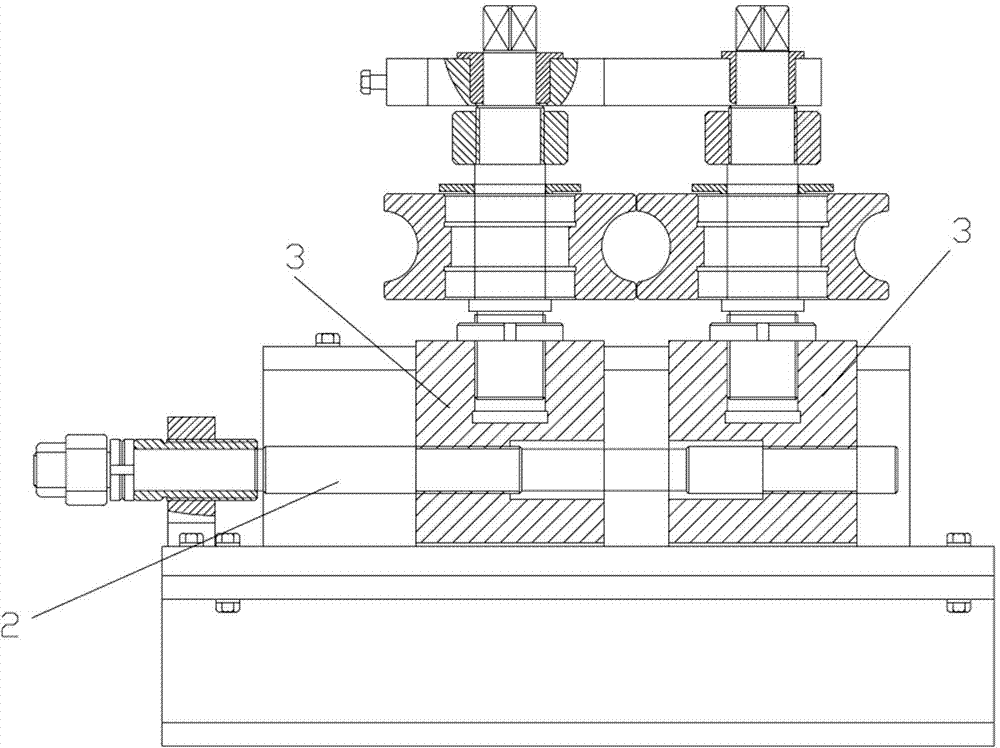
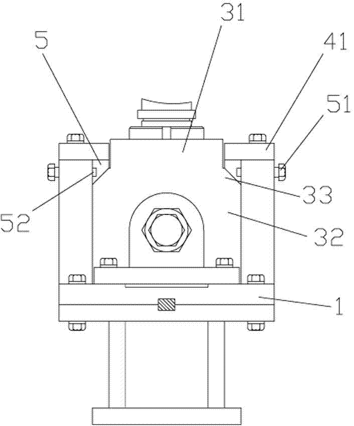
[0028] An improved structure of a welded pipe extrusion roller seat, comprising a pinch wheel base plate 1, a screw rod 2 arranged on the pinch wheel base plate 1, a slider 3 sleeved on the screw rod 2 and driven by the screw rod 2, a set The extrusion mechanism on the slider 3 and the position-limiting guide wall panels 4 on both sides of the slider are arranged on the pressure wheel base plate 1. The slider 3 includes a connecting section 31 on the upper part and a guiding transmission section 32 on the lower part. The top of the guide transmission section 32 is located at the both sides of the connecting section 31 as the limit shoulder 33, the top of the limit guide wall plate 4 is provided with a pressure plate 41, and a correction strip 5 is provided between the limit shoulder 33 and the pressure plate 41, and the outside of the correction strip 5 is provided with A plurality of correcting components 51 pressed against the correcting bar 5 to indirectly correct the slider...
Embodiment 2
[0032] The difference from the above embodiment is that the angle between the straightening surface and the horizontal plane is 30 degrees, and two bolts are arranged along the straightening groove.
Embodiment 3
[0034] The difference from the above embodiment is that the angle between the straightening surface and the horizontal plane is 60 degrees, and five bolts are arranged along the straightening groove.
[0035] How many bolts are provided can be selected according to the length and size of the slide block.
[0036] When the slider is twisted or deflected in the horizontal or gravity direction, adjust the correcting part at the corresponding position, that is, the bolt, so that the correction bar applies a greater force or reduces the applied force to the twisted part of the slider, and the slider is moved by external force. Correction, no need to disassemble or replace parts, and can be corrected from time to time, which not only ensures the normal sliding of the slider, but also ensures that the slider does not deflect, so as to ensure the high roundness of the steel pipe extruded by the extrusion mechanism.
[0037] By setting the correction bar on the limit shoulder of the sl...
PUM
 Abstract
Description
Claims
Application Information