
Mechanical arm device

A technology of manipulators and rotating platforms, which is applied in the field of multi-manipulator cycle work devices, can solve the problems of low work efficiency, high labor intensity of workers, and high risk of workers, and achieve the effect of reducing labor intensity, stable and reliable working process, and ensuring safety

Inactive Publication Date: 2014-01-08
邓刚锋
View PDF5 Cites 6 Cited by
  • Summary
  • Abstract
  • Description
  • Claims
  • Application Information

AI Technical Summary

Problems solved by technology

In this manual feeding and discharging mode of the ceramic molding machine, the labor intensity of the workers is high, the work efficiency is low, and the danger of the workers is also high.

Method used


Image

  • Mechanical arm device
  • Mechanical arm device
  • Mechanical arm device

Examples


Embodiment Construction

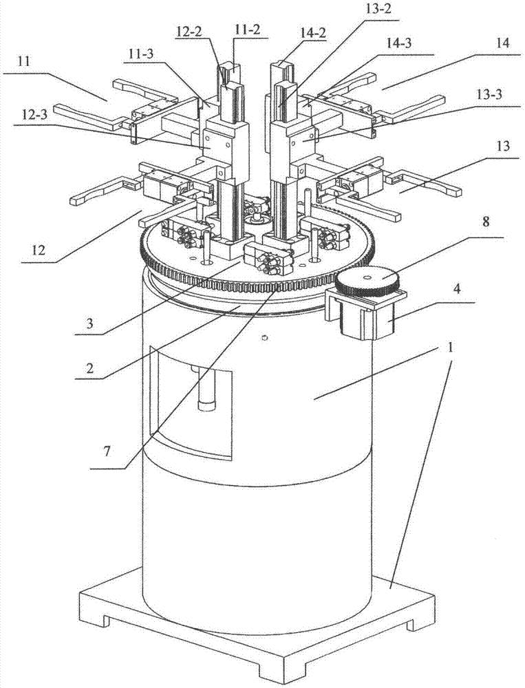
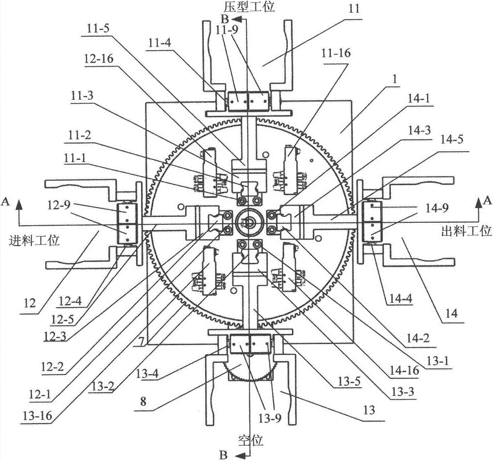
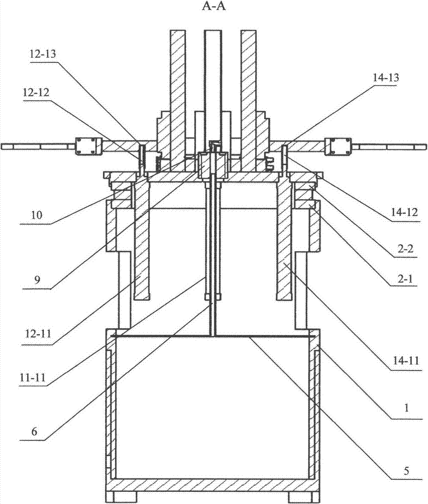
[0018] Such as figure 1 , figure 2 , image 3 , Figure 4 , Figure 5 , Figure 6 , Figure 7 As shown: the manipulator device is mainly composed of chassis 1, bearing 2, rotating platform 3, motor 4, No. 1 manipulator 11, No. 2 manipulator 12, No. 3 manipulator 13, No. 4 manipulator 14, guide rail 11-2, guide rail 12-2 , Guide rail 13-2, guide rail 14-2, slide block 11-3, slide block 12-3, slide block 13-3, slide block 14-3 form.

[0019] The bearing lower end surface 2-1 is fixedly connected to the chassis 1, and the bearing upper end surface 2-2 is fixedly connected to the rotating platform 3, so that the rotating platform 3 can rotate relative to the chassis 1. The ring gear 7 is fixedly connected to the rotating platform 3, and the motor 4 drives the ring gear 7 through the driving gear 8 installed thereon, and then drives the rotating platform 3 to rotate. Since No. 1 manipulator 11, No. 2 manipulator 12, No. 3 manipulator 13, and No. 4 manipulator 14 have the sa...


PUM


Abstract

The invention relates to a mechanical arm device, in particular to a multi-mechanical-arm circulation working device which is used for feeding and discharging procedures of a ceramic molding press. According to the technical scheme, the multi-mechanical-arm working device comprises a chassis 1, a bearing 2, a rotating platform 3, a motor 4 and mechanic arms 11,12,13,14. The bearing 2 is installed between the chassis 1 and the rotating platform 3 to ensure that the rotating platform 3 can rotate relative to the chassis 1; the mechanical arm 11,12,13,14 are fixedly connected with sliding blocks 11-3, 12-3, 13-3, 14-3 respectively to achieve sliding of guide rails 11-2,12-2,13-2,14-2. Lifting air cylinders are installed below the mechanical arms respectively and can achieve rise and descent of the mechanical arms, and each mechanical arm is provided with two clamping air cylinders and can achieve clamping and opening of mechanical arm clamping pieces; rotating of the rotating platform 3 is driven by the motor 4 through a gear transmission device.

Description

technical field [0001] The invention relates to a manipulator device, in particular to a multi-manipulator cycle working device used in the feeding and discharging process of a ceramic molding machine. Background technique [0002] Forming machines are well known. In the existing ceramic production process with a ceramic molding machine as the main equipment, the process of placing the mud and molds in the steel mold of the ceramic molding machine is done manually. Ceramic molding workers place the mold with mud in the steel mold of the ceramic molding machine, wait for the pressure head of the molding machine to press into the mold with mud and shape the mud, and then put the formed ceramic mud The blank and the mold are taken out of the steel mold of the ceramic molding machine, and then the process is repeated. Under the feeding and discharging mode of this manual ceramic molding machine, the labor intensity of the workers is high, the work efficiency is low, and the ri...

Claims


Application Information

Patent Timeline
Patent Type & Authority Applications(China)
IPC IPC(8): B28B3/02
CPCB28B17/00B28B3/02
Inventor 邓刚锋
Owner 邓刚锋
Learn More