
Method for monitoring and judging working states of ring spinning frame

A working state, spinning frame technology, applied in textiles and papermaking, etc., can solve the problems of requiring air source, high investment cost, difficult sensitive, stable and reliable operation of the system, etc., to achieve the effect of stable characteristic curve and high inspection frequency

Active Publication Date: 2015-07-01
苏州盛泽科技创业园发展有限公司
View PDF4 Cites 0 Cited by
  • Summary
  • Abstract
  • Description
  • Claims
  • Application Information

AI Technical Summary

Problems solved by technology

The system is mainly composed of a mechanical mechanism and a pneumatic mechanism, so the structure is relatively complex, the investment cost is high, the maintenance is difficult, and an air source is required
In the multi-spindle and bad working conditions of spinning production, it is difficult to ensure the stability of the air pressure, so it is difficult for the system to operate sensitively, stably and reliably

Method used

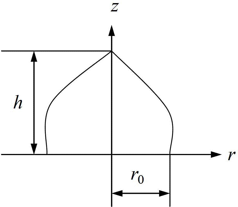
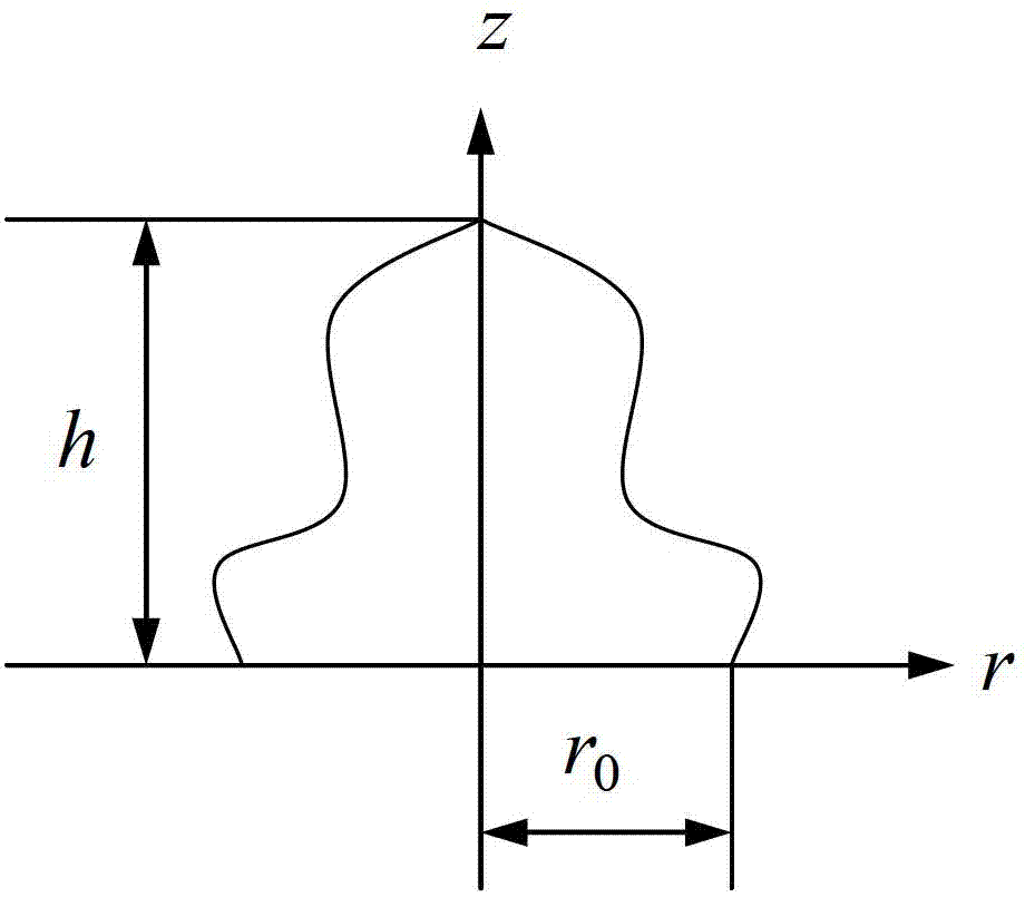

Image

  • Method for monitoring and judging working states of ring spinning frame
  • Method for monitoring and judging working states of ring spinning frame
  • Method for monitoring and judging working states of ring spinning frame

Examples


Embodiment Construction

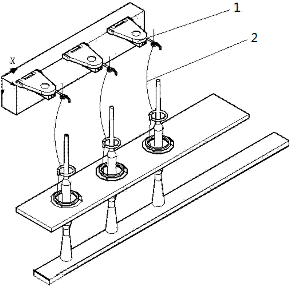
[0043] Such as image 3 In a preferred embodiment shown, the photodetection device 1 composed of a luminescent tube and a photoelectric receiver is installed on the yarn guide hook. The light-emitting tube corresponding to each bobbin coil and the probe of the photoelectric receiving device are installed on the balloon yarn path 2 of the spinning frame. The intersection point of the emitting central axis of the probe luminous tube and the receiving central axis of the photoelectric receiving device is located above the yarn balloon in the yarn path, so the yarn balloon serves as a reflecting surface. When the luminescent tube and the photoelectric receiving device work, the yarn When the air circle passes through the intersection of the light-emitting tube and the photoelectric receiving device, the light received by the photoelectric receiving device passes through such as Figure 4 The circuit shown is for signal processing. The formed balloon signal of the yarn is passed ...


PUM


Abstract

The invention discloses a method for monitoring the working state of a ring spinning frame, which is characterized in that: an induction device is installed in the sensing area of ​​the spinning frame balloon, and the induction device senses the digital signal generated by the rotation of the spinning balloon, and outputs The digital signal is analyzed to judge the working status of the ring spinning machine. The method of judging the working state of the ring spinning frame is calibrated by monitoring the output digital signal amplitude and the distance between the actual sensing device and the yarn balloon, and according to the frequency and amplitude maximum and minimum values ​​of the digital signal within a certain period of time , The average value is compared with the set value to analyze the working state of the spinning frame. The invention has the advantages of simple structure, high inspection frequency and stable signal characteristic curve; it can count and calculate the size of the balloon and the rotating speed of the balloon; it can comprehensively diagnose the working state of the spinning frame and perform alarms for various faults.

Description

technical field [0001] The invention belongs to the technical field of textiles, and in particular relates to a monitoring method and a judging method for the working state of a ring spinning frame. Background technique [0002] The spinning process is the last process of spinning in the spinning process. The production efficiency, yarn quality, machine material consumption, energy consumption, labor and other indicators are the embodiment of the production technology level and management level of textile enterprises. An important duty of the spun yarn stopper in a textile mill is to check and deal with broken yarns, and most of the time is spent on roving checks on broken yarns. Especially when spinning dark-colored yarns, end-break inspection is more difficult because the contrast between the yarn color and the environment is not strong. Therefore, whether it is possible to establish a spun yarn breakage detection system that can adapt to a variety of ring spinning spun y...

Claims


Application Information

Patent Timeline
Patent Type & Authority Patents(China)
IPC IPC(8): D01H13/16D01H13/32
Inventor 刘基宏徐阳刘建立高卫东
Owner 苏州盛泽科技创业园发展有限公司
Learn More