Parallel type self-balancing multi-stage centrifugal pump

A self-balancing, centrifugal pump technology, applied in the field of centrifugal pumps, can solve problems such as head range and cavitation performance that are difficult to meet, and achieve the effects of prolonging trouble-free working time, excellent cavitation performance, and improving working conditions

Inactive Publication Date: 2014-01-08
CHANGSHA CANON GENERAL PUMPS
View PDF5 Cites 6 Cited by
  • Summary
  • Abstract
  • Description
  • Claims
  • Application Information

AI Technical Summary

Problems solved by technology

However, the head range and cavitation performance of double-suction split pumps are difficult to meet the requirements of occasions such as water intake from long-distance water sources, mine drainage with large water volume, etc.

Method used


Image

  • Parallel type self-balancing multi-stage centrifugal pump

Examples


Embodiment Construction

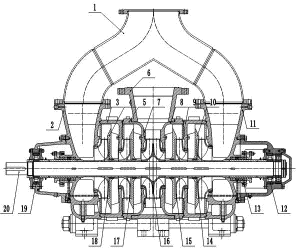
[0011] Such as figure 1 As shown, a parallel self-balancing multistage centrifugal pump includes a pump body 5 and a main shaft 20. A shaft seal device 13 is provided on both sides of the main shaft 20. The main shaft 20 passes through a left bearing body part 19 and a right bearing body part. 12 is fixed on the pump body 5, the positive front impeller 18, the positive impeller 17, the positive guide vane 4, the reverse impeller 15, the reverse guide vane 10 and the reverse front impeller 14 are arranged symmetrically back to back on the main shaft, and the middle impeller 16 And the middle guide vane 7 is installed in the middle of the main shaft 20, the positive front impeller 18, positive impeller 17 and positive guide vane 4 are located in the left middle section 3 of the pump body, and the reverse front impeller 14, reverse impeller 15 and Anti-guide vanes 10 are located in the right middle section 9 of the pump body.

[0012] When the water pump is running, the water is...


PUM


Abstract

The invention discloses a parallel type self-balancing multi-stage centrifugal pump. Due to the fact that impellers are symmetrically arranged in a pump body in a back-to-back mode, self balancing of the impellers in the axial direction is achieved, mechanical friction generated by axial force in the rotation process of the multi-stage centrifugal pump is reduced, and service life of the centrifugal pump is prolonged. Due to the fact that a balancing structure is removed from the centrifugal pump, wearing parts are few, leakage losses are small, safety and reliability are high, and maintaining is easy.

Description

technical field [0001] The invention relates to a centrifugal pump, in particular to a self-balancing multistage centrifugal pump. Background technique [0002] At present, multi-stage centrifugal pumps are mainly used in occasions with relatively small flow and high lift; however, double-suction split pumps are mainly used in occasions with large flow and low lift. When multiple pumps are running, due to the pressure difference between the water inlet and the water outlet, an axial force directed to the water inlet will be generated. In order to balance the axial force, balance mechanisms such as balance holes, balance ribs, balance drums, and balance discs are usually used. However, these balancing measures generally have disadvantages such as many wearing parts, large leakage loss, increased power consumption, and unreliable balancing effects. Especially for the balance plate mechanism of multiple pumps, it is easy to wear, troublesome to disassemble, and difficult to m...

Claims


Application Information

Patent Timeline
Patent Type & Authority Applications(China)
IPC IPC(8): F04D1/10
Inventor 罗瑞祥黄发
Owner CHANGSHA CANON GENERAL PUMPS
Why Eureka
Try Eureka