Two-hand rubbing simulation mechanism

A two-handed, frame-based technology, applied to mechanical equipment, transmission devices, belts/chains/gears, etc., can solve the problems of high cost, high cost, complex structure, etc., and achieve high work reliability, widely popularized and used, and simple structure Effect

Inactive Publication Date: 2014-01-08
SUZHOU ROARING PRECISION MASCH CO LTD
View PDF9 Cites 1 Cited by
  • Summary
  • Abstract
  • Description
  • Claims
  • Application Information

AI Technical Summary

Problems solved by technology

This not only makes the whole device extremely large and complex, but also extremely expensive
Such as the kneading massager disclosed in Chinese patent document CN 102940566 A, not only the structure is extremely complicated, but also fails to give the trajectory of bionic motion; another example is the numerical control rubbing type grinding machine disclosed in Chinese patent document CN 103252709 A, then adopted 3 servo The motor, as well as the extremely complex mechanical transmission system, is bulky and expensive
From the perspective of kinematics, no substantial hands-rubbing bionic mechanism has been retrieved so far

Method used


Image

  • Two-hand rubbing simulation mechanism
  • Two-hand rubbing simulation mechanism
  • Two-hand rubbing simulation mechanism

Examples


Embodiment 1

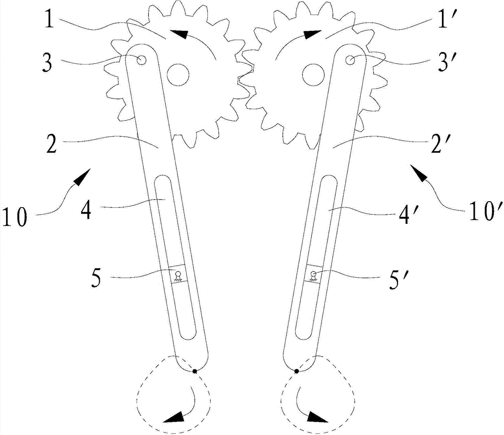
[0025] see figure 1 , figure 2 The shown hands-rubbing bionic mechanism includes a frame (not shown in the figure), and two sets of rubbing components 10, 10' arranged on the frame.

[0026] The kneading assembly 10 includes a gear 1 rotatably arranged on the frame around the axis, and a connecting rod 2 rotatably arranged on the gear 1 through a pin shaft 3 . There is an eccentric pin hole on the gear 1, the center line of the pin hole is parallel to the axis line of the gear 1, one end of the pin shaft 3 is connected to the upper part of the connecting rod 2, and the other end is rotatably passed through the above pin hole middle. A chute 4 is provided on the connecting rod 2, and the chute 4 extends along the length direction of the connecting rod 2. The frame is provided with a slider 5 hinged at the center on the frame for providing the guidance of the connecting rod 2, that is, the slider 5 The center positions of the two axial ends of the shaft are hinged on th...

Embodiment 2

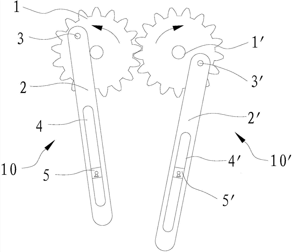
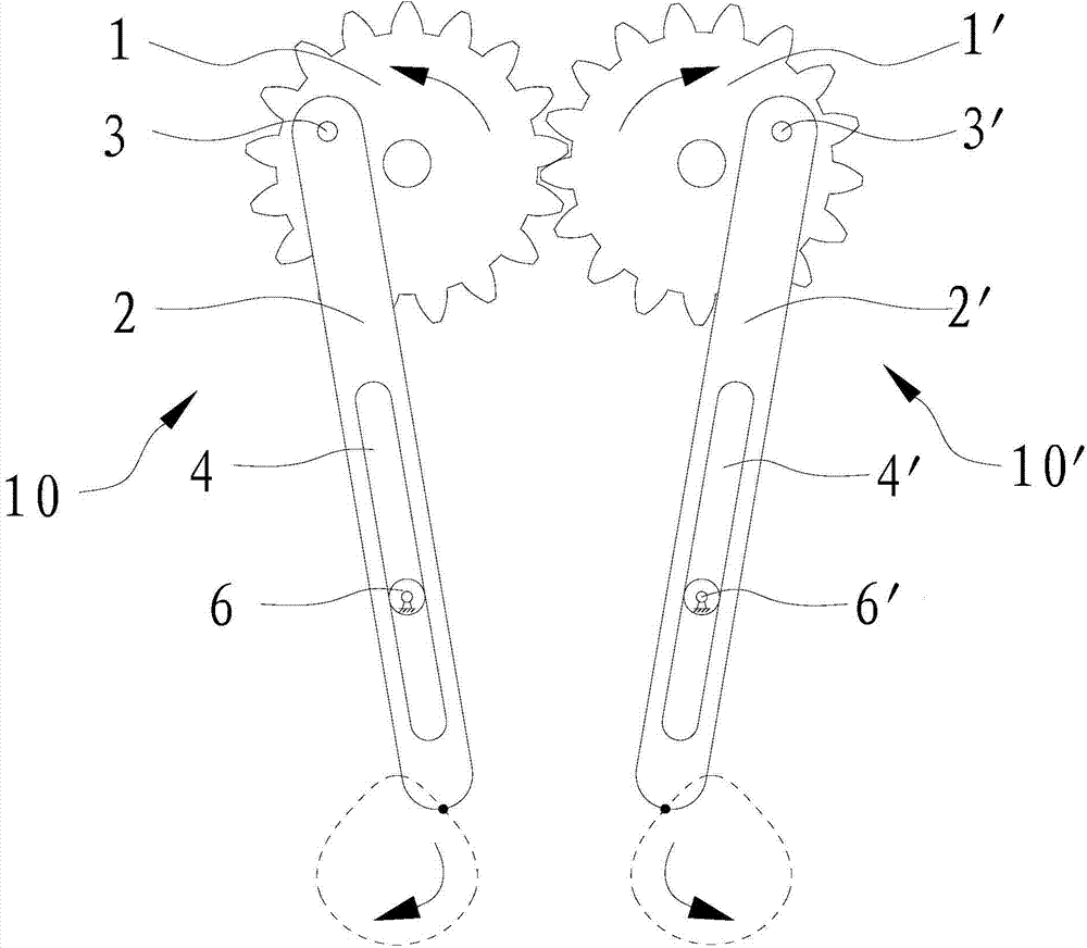
[0035] see image 3 Shown both hands kneads bionic mechanism, the difference of this bionic mechanism and embodiment 1 mainly lies in the setting of the parts that provide connecting rod 2, 2 ' guide. In this embodiment, the guide member 6, 6' provided on the frame is centered on the part providing the guide of the connecting rod 2, 2', and the guide member 6, 6' is respectively arranged in the chute 4, 4' with loose fit. Among them, the circumferential outer surface of the guides 6, 6' matched with the longitudinal groove walls of the chute 4, 4' is a cylindrical surface, and the guides 6, 6' form a plane height pair with the chute 4, 4' respectively. When the external driving mechanism drives one of the gears 1 and 1' to rotate, the connecting rods 2 and 2' are respectively operated by the pin shafts 3 and 3' relative to the guides 6 and 6' on the cylindrical outer surface. The rectilinear motion swings again, so that the lower ends of the connecting rods 2, 2' can produc...


PUM


Abstract

The invention discloses a two-hand rubbing simulation mechanism which comprises a rack and two sets of rubbing components arranged on the rack. Each rubbing component comprises a gear, a connecting rod, a sliding block with the center hinged to the rack or a guide piece with a cylindrical outer surface, the centers of the guide pieces are fixed to the rack, sliding grooves extending in the length directions of the connecting rods are formed in the connecting rods, the sliding blocks or the guide pieces are arranged in the sliding grooves in an interference fit mode to guide the connecting rods, the two gears on the rubbing components are meshed, and when an external drive mechanism drives the gear on one rubbing component to rotate, the lower ends of the connecting rods of the rubbing components can generate the simulation movement similar to two-hand rubbing. The simulation mechanism achieves the complex plane movement simulating the two-hand rubbing through few parts, is extremely simple in structure, low in manufacturing cost and high in work reliability, can meet the needs of all kinds of corresponding products for the two-hand rubbing simulation mechanism with the extremely low manufacturing cost, and has good practicability.

Description

[0001] technical field [0002] The invention relates to a bionic mechanism for rubbing hands. Background technique [0003] In the innovative design of the mechanism, it is extremely difficult to imitate the movement of human hands by relying solely on the movement of the mechanism itself. Because the movement of human hands rubbing is a compound motion of linear motion and swing. Using numerical control technology to imitate the action of human rubbing is the easiest technical solution to think of. However, using numerical control technology to imitate the movement of rubbing with one hand requires at least two servo motors, which are programmed and driven by a two-axis linkage numerical control system; system control to achieve. This not only causes the whole device to be extremely large and complex, but also extremely expensive. Such as the rubbing massager disclosed in Chinese patent document CN 102940566 A, not only the structure is extremely complex, but also fail...

Claims


Application Information

Patent Timeline
Patent Type & Authority Applications(China)
IPC IPC(8): F16H37/12
CPCF16H37/122F16H37/126
Inventor 窦云霞王传洋钟康民
Owner SUZHOU ROARING PRECISION MASCH CO LTD
Why Eureka
Try Eureka