Double-resonant cavity resonant optic gyro

A double-resonant cavity and optical gyroscope technology, which is applied in Sagnac effect gyroscopes, gyroscopes/steering sensing equipment, measuring devices, etc., can solve the problem of low sensitivity of resonant optical gyroscopes and improve sensitivity and test accuracy , Improve the frequency locking accuracy, improve the effect of quality factor Q value

Active Publication Date: 2014-01-08
ZHONGBEI UNIV
View PDF5 Cites 15 Cited by
  • Summary
  • Abstract
  • Description
  • Claims
  • Application Information

AI Technical Summary

Problems solved by technology

[0003] In order to solve the problem of low sensitivity of the resonant optical gyroscope, the present invention provides a double resonant cavity resonant optical gyroscope

Method used


Image

  • Double-resonant cavity resonant optic gyro
  • Double-resonant cavity resonant optic gyro
  • Double-resonant cavity resonant optic gyro

Examples


Embodiment Construction

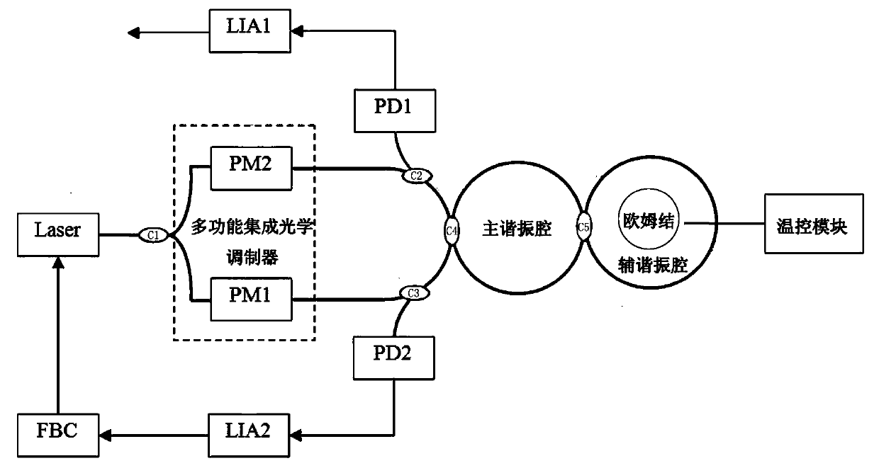
[0013] The dual-cavity resonant optical gyroscope includes an isolated collimation chip tunable light source Laser, the output end of the isolated collimation chip tunable light source Laser is connected to the input end of the first coupler C1 through an optical waveguide, and the output end of the first coupler C1 The terminals are respectively connected to the input terminals of the first modulator PM1 and the second modulator PM2 in the multifunctional integrated optical modulator through the optical waveguide, and the output terminal of the first modulator PM1 is connected with the input terminal of the third coupler C3 through the optical waveguide , the output end of the second modulator PM2 is connected to the input end of the second coupler C2 through the optical waveguide, and the output ends of the second coupler C2 and the third coupler C3 are respectively connected to the input end of the fourth coupler C4 through the optical waveguide connection, the output end of...


PUM


Abstract

The invention relates to a high-sensitivity resonant optic gyro, and particularly relates to a double-resonant cavity resonant optic gyro which comprises an isolation collimation chip tunable light source Laser, a first coupler C1, a multifunctional integrated optic modulator, a third coupler C3, a second coupler C2, a fourth coupler C4, a main resonant cavity, a first photoelectric detector PD1, a first lock-in amplifier LIA1, a second photoelectric detector PD2, a second lock-in amplifier LIA2, and a feedback control circuit FBC, and also comprises a circular auxiliary resonant cavity with an ohmic contact disposed at the central position, a temperature control module and a fifth coupler C5; an output port is disposed at a position opposite to an input port on the main resonant cavity; an input end of the fifth coupler C5 contacts the output port of the main resonant cavity; an output end of the fifth coupler C5 contacts an input port of the auxiliary resonant cavity; the temperature control module is connected with the ohmic contact through wires made by MEMS technology; and the invention solves the problem of low sensitivity of optic gyros.

Description

technical field [0001] The invention relates to a high-sensitivity resonant optical gyroscope, in particular to a double-cavity resonant optical gyroscope. Background technique [0002] Resonant optical gyroscope is a new type of angular velocity sensor with small size, low power consumption and high reliability developed after MEMS gyroscope, interferometric fiber optic gyroscope and laser gyroscope. Driven by major plans and projects such as , high sensitivity, miniaturization, high stability, and high overload resistance have become the development trend of gyro inertial devices in the future, and high sensitivity is the primary indicator of resonant optical gyroscopes. In recent years, the research of resonant optical gyroscope has received extensive attention from research institutions at home and abroad, and some research results have been obtained. The output end is connected to the input end of the first coupler C1 through the optical waveguide, and the output end o...

Claims


Application Information

Patent Timeline
Patent Type & Authority Applications(China)
IPC IPC(8): G01C19/64
CPCG01C19/722G01C19/727
Inventor 闫树斌郑永秋薛晨阳任勇峰李圣昆张文栋刘俊焦新泉安盼龙张蔚云张建辉李小枫
Owner ZHONGBEI UNIV
Why Eureka
Try Eureka