Measurement method of voltage division ratio of voltage-sharing capacitor for spark gap of series capacitor compensation device

A series capacitance compensation and spark gap technology, which is applied to measuring devices, measuring electrical variables, measuring current/voltage, etc., can solve the problems of low test accuracy, complex test process, poor efficiency, etc., to improve test accuracy and simplify test steps. , the effect of reducing the number of tests

Active Publication Date: 2014-01-08
EXAMING & EXPERIMENTAL CENT OF ULTRAHIGH VOLTAGE POWER TRANSMISSION COMPANY CHINA SOUTHEN POWER GRID
View PDF4 Cites 8 Cited by
  • Summary
  • Abstract
  • Description
  • Claims
  • Application Information

AI Technical Summary

Problems solved by technology

[0004] Based on this, it is necessary to provide a series capacitance compensation device spark gap for the existing technical problems of low test accuracy, complicated test process and poor efficiency in the measurement of the voltage dividing ratio of the equalizing capacitor for the spark gap of the series capacitor compensation device. Measuring Method of Divider Ratio of Voltage Equalizing Capacitor

Method used


Image

  • Measurement method of voltage division ratio of voltage-sharing capacitor for spark gap of series capacitor compensation device
  • Measurement method of voltage division ratio of voltage-sharing capacitor for spark gap of series capacitor compensation device
  • Measurement method of voltage division ratio of voltage-sharing capacitor for spark gap of series capacitor compensation device

Examples


Embodiment Construction

[0030] The present invention will be described in further detail below in conjunction with the accompanying drawings and specific embodiments.

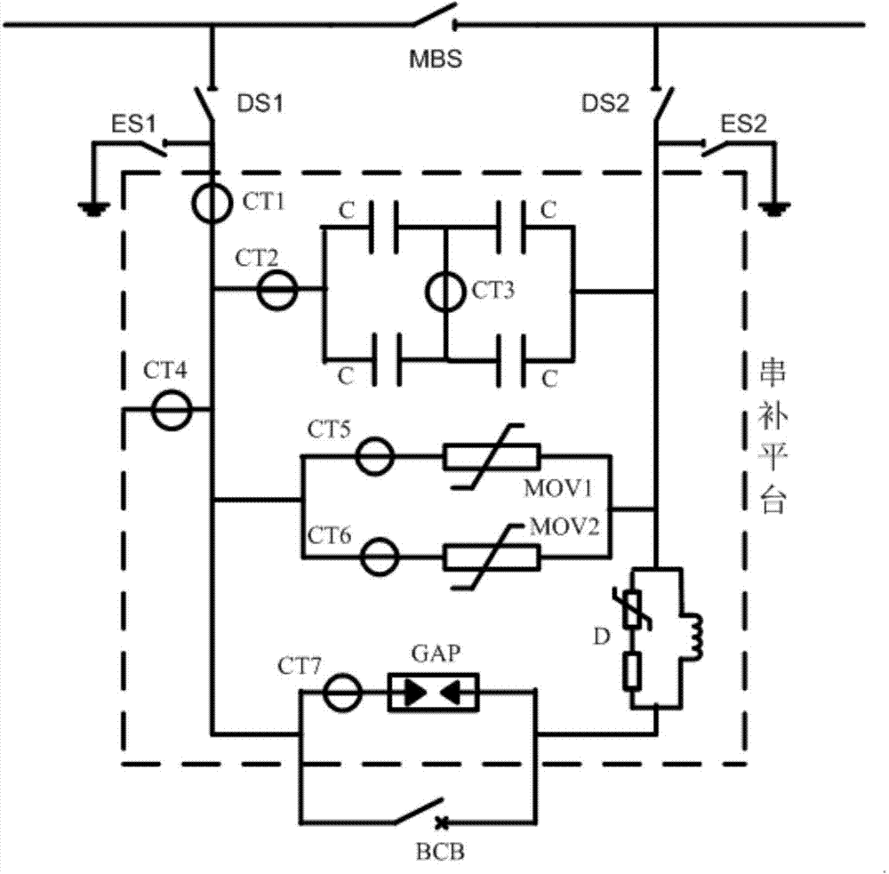
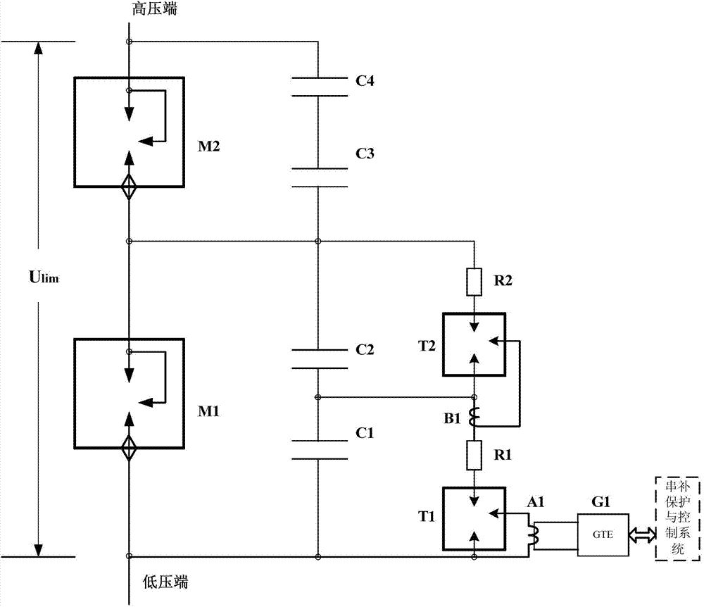
[0031] Such as Figure 4 Shown is a working flow chart of a method for measuring the voltage-dividing ratio of voltage-equaling capacitors used in the spark gap of a series capacitor compensation device according to the present invention. The series capacitor compensation device includes at least two spark gap branches and at least two capacitor branches, Each spark gap branch includes at least one spark gap, and each capacitor branch includes at least one capacitor, wherein the first spark gap branch is connected in parallel with the first capacitor branch to form a first spark capacitor branch, and the second spark gap branch It is connected in parallel with the second capacitor branch to form a second spark capacitor branch. One end of the first spark capacitor branch is a low-voltage end, and the other end of the first spark capac...


PUM


Abstract

The invention relates to the technical field related to a series capacitor compensation device, in particular to a measurement method of the voltage division ratio of a voltage-sharing capacitor for a spark gap of the series capacitor compensation device. The method comprises the steps of disconnecting the electrical connection between a first capacitor branch circuit and a low-voltage end and / or disconnecting the electrical connection between a second capacitor branch circuit and a high-voltage end; respectively applying the same test voltage at the two ends of the first capacitor branch circuit and the second capacitor branch circuit, and controlling the frequency of the test voltage to be more than or equal to 50Hz; measuring the current of the first capacitor branch circuit to obtain first capacitor branch circuit current, and measuring the current of the second capacitor branch circuit to obtain the second capacitor branch circuit current; taking the inverse ratio of the current ratio of the first capacitor branch circuit current and the second capacitor branch circuit current as the voltage division ratio of the first capacitor branch circuit and the second capacitor branch circuit. After the method capable of improving the test frequency is adopted, the test voltage can be reduced to be lower than the safe voltage of 50V under the condition of meeting the requirements of test current, so that the test safety is improved, and the measurement method has very high power frequency interference resistance.

Description

technical field [0001] The invention relates to the related technical field of a series capacitor compensation device, in particular to a method for measuring the voltage division ratio of a voltage equalizing capacitor used in a spark gap of a series capacitor compensation device. Background technique [0002] The series capacitor compensation device can improve the transmission capacity and stability of the system, and its working principle is shown in the appendix figure 1 , where GAP is the spark gap and D is the damping circuit. Spark gaps are critical protective devices for series capacitors. The voltage limiter (MOV) is the main protection for series capacitors, i.e. figure 1 In MOV1 and MOV2, the spark gap is the main protection of the MOV and the backup protection of the series capacitor. When a serious short-circuit fault occurs in the system, the capacitor is quickly overvoltage, and the MOV protection starts. Due to the limited energy bearing of the MOV, the s...

Claims


Application Information

Patent Timeline
Patent Type & Authority Applications(China)
IPC IPC(8): G01R19/10
Inventor 唐金昆朱坚王奇顾保全
Owner EXAMING & EXPERIMENTAL CENT OF ULTRAHIGH VOLTAGE POWER TRANSMISSION COMPANY CHINA SOUTHEN POWER GRID
Why Eureka
Try Eureka