
Acoustic sensor and method for manufacturing same

A sound sensor and substrate technology, applied in the direction of sensors, sensor parts, electrostatic transducer microphones, etc., can solve the problems of the decrease of the sensitivity of the sound sensor, the deterioration of the sensitivity characteristics, the leakage of the space in the box, etc., to improve the fixing strength and stability. , The effect of preventing the deterioration of the sensitivity characteristics and the increase of the acoustic resistance

Inactive Publication Date: 2014-01-08
ORMON CORP
View PDF8 Cites 2 Cited by
  • Summary
  • Abstract
  • Description
  • Claims
  • Application Information

AI Technical Summary

Problems solved by technology

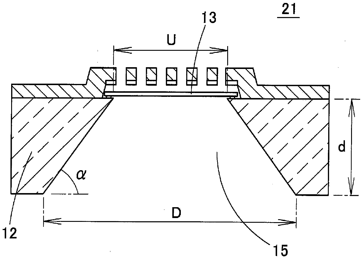
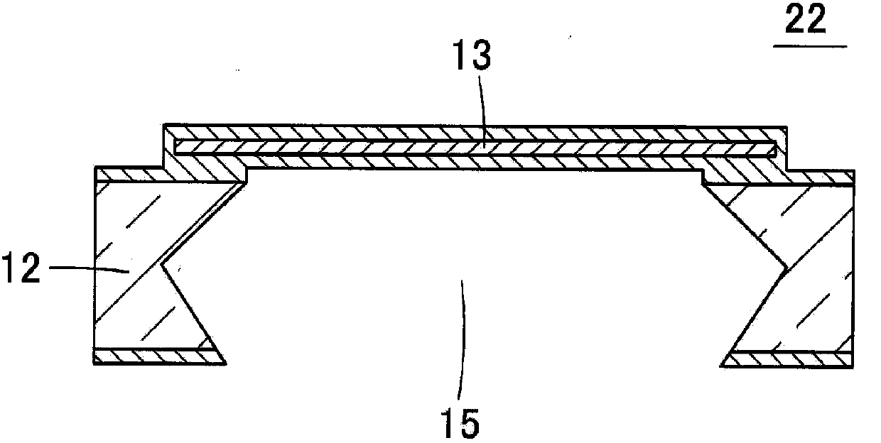
Therefore, like the acoustic sensor of Patent Document 3, the acoustic vibration entering the cavity 15 is as follows: Figure 8 It is easy to leak to the inner space of the box through the vent hole 31 and the etching hole 29 as shown by the arrow in
As a result, the sensitivity of the acoustic sensor is reduced, especially in the low frequency region, and the sensitivity characteristics are significantly deteriorated

Method used


Image

  • Acoustic sensor and method for manufacturing same
  • Acoustic sensor and method for manufacturing same
  • Acoustic sensor and method for manufacturing same

Examples


no. 1 approach

[0102] (Acoustic sensor of the first embodiment)

[0103] Figure 10 It is a sectional view showing the structure of the acoustic sensor 41 according to the first embodiment of the present invention. The acoustic sensor 41 has a substrate 42 , a film-shaped diaphragm 43 , a back plate 45 , and fixed electrodes 46 . The substrate 42 is a (100)-plane Si substrate whose front and back are (100) planes. A cavity 44 is formed in the substrate 42 to penetrate the front and back surfaces by etching from the back side. The cavity 44 has wall surfaces in four directions, and when viewed from a direction perpendicular to the surface of the substrate 42, as Figure 11 As shown, the cavity 44 has a rectangular shape with each side facing the (110) direction or a direction equivalent to the (110) direction.

[0104] Figure 10 shows the sound sensor 41 along the Figure 11 The cross-section of the K-K line. Each wall surface of the cavity 44 includes a first slope 47 a and a second ...

no. 2 approach )

[0135] Figure 19 (A) is a sectional view of the acoustic sensor 81 according to the second embodiment of the present invention. In this acoustic sensor 81 , the heights H3 and H4 of the nodes P are different between the opposing wall surfaces of the cavity 44 , and the cross-sectional shapes of the wall surfaces are different from each other. At this time, the height H4 of one node P is larger than 1 / 2 of the thickness of the substrate 42, but the height H3 of the other node P can be larger than 1 / 2 of the thickness of the substrate 42 or smaller than the thickness of the substrate 42. half of the thickness.

[0136] In order to form such an asymmetric cavity 44, in the method of manufacturing the acoustic sensor described in the first embodiment, when the through-hole 76 is opened in the substrate 42 by dry etching, as Figure 19 As shown in (B) in (B), the center of the through hole 76 may be shifted from the center of the sacrificial layer 71 in the horizontal direction....


PUM


Abstract

A cavity (44) is provided in a substrate (42) so as to penetrate from the front surface to the back surface of the substrate (42). A thin-film diaphragm (43) for sensing acoustic vibration above the substrate (42) is provided over the cavity (44). At least one wall surface of the cavity (44) is configured with: a first inclined surface (47a) between the front surface of the substrate (42) and the center portion of the substrate (42) in the thickness direction, the inclined surface gradually widening toward the outer side of the substrate (42) from the front surface of the substrate (42) toward the center portion; and a second inclined surface (47b) between the center portion and the back surface of the substrate (42), the inclined surface gradually narrowing toward the inner side of the substrate (42) from the center portion toward the back surface of the substrate (42). Furthermore, the width of the back-surface opening of the cavity (44) is smaller than the width of the front-surface opening.

Description

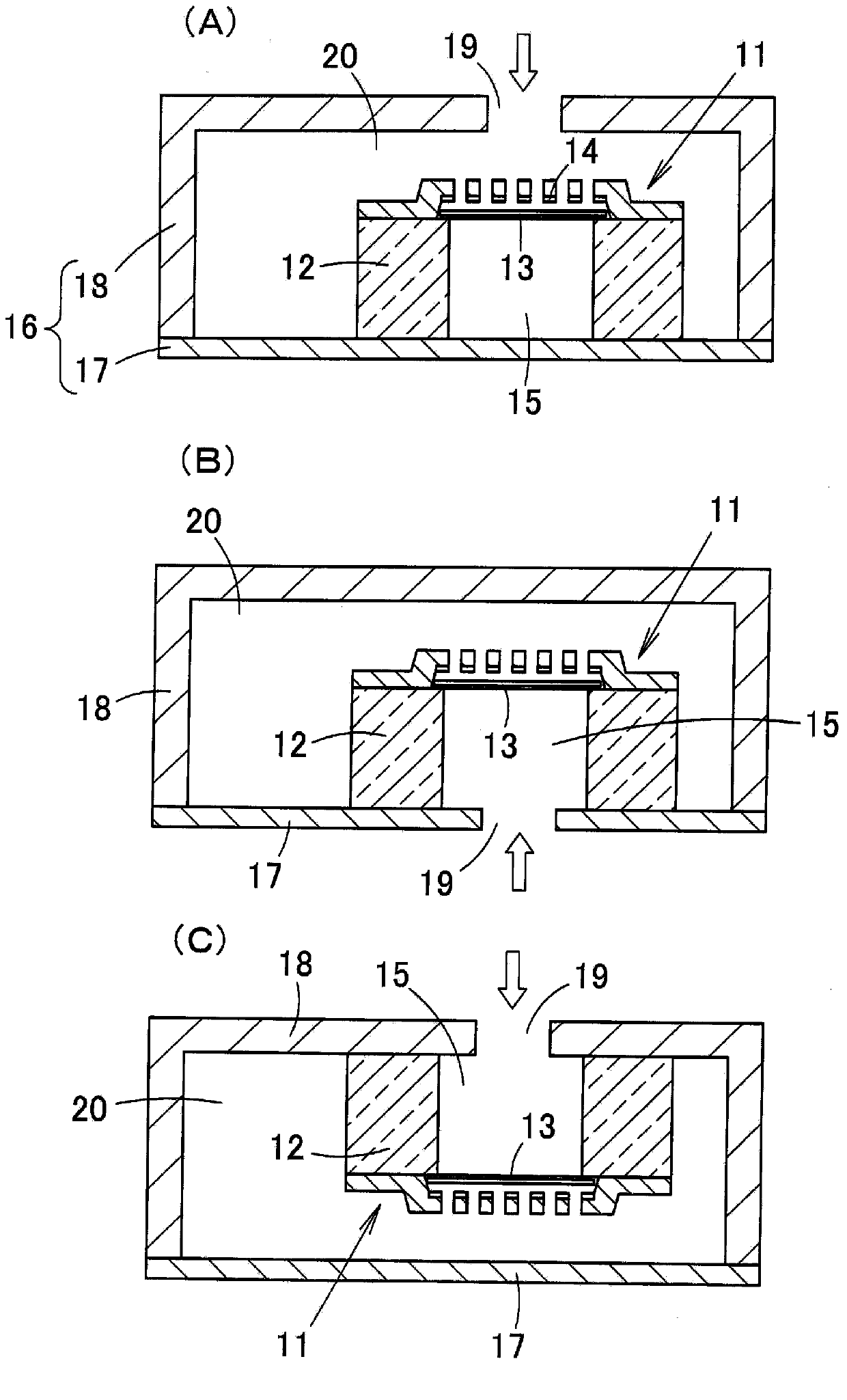
technical field [0001] The present invention relates to an acoustic sensor and a manufacturing method thereof, and particularly to an acoustic sensor usable as a high-sensitivity microphone (Microphone) and a manufacturing method thereof. Background technique [0002] figure 1 (A) in figure 1 (B) in and figure 1 (C) is a cross-sectional view showing a microphone module in which a conventional acoustic sensor is accommodated in a housing. Acoustic sensor 11 has thin-film diaphragm 13 (movable electrode) and fixed electrode 14 provided on the surface of substrate 12 , and cavity 15 is formed in substrate 12 on the rear side of diaphragm 13 . This acoustic sensor 11 is an electrostatic capacitive sensor that detects acoustic vibrations by utilizing a change in electrostatic capacity between a diaphragm 13 and a fixed electrode 14 . The box 16 includes a base 17 and a cover 18 covering the base 17 . [0003] As far as the sound sensor 11 is concerned, initially as figure 1...

Claims


Application Information

Patent Timeline
Patent Type & Authority Applications(China)
IPC IPC(8): H04R19/04H01L29/84H04R31/00
CPCB81B3/0027H04R31/00H04R1/2807H04R19/04H04R19/005B81C1/00531
Inventor 中河佑将多田罗佳孝饭田信行石本浩一滨口刚叶肇
Owner ORMON CORP
Learn More