Hair drying cap

A hair drying cap and cap body technology, applied in the field of hair drying caps, can solve problems such as air permeability and intelligence of hair drying appliances that cannot be solved, achieve the effect of shortening the evaporation time of water, accelerating the evaporation time of water, and having a good promotion prospect

Active Publication Date: 2014-01-15
SHENZHEN INST OF ADVANCED TECH CHINESE ACAD OF SCI
View PDF13 Cites 7 Cited by
  • Summary
  • Abstract
  • Description
  • Claims
  • Application Information

AI Technical Summary

Problems solved by technology

[0005] To sum up, among the several existing hair dryers, the problems of air permeability and intelligence of the hair dryer still cannot be solved.

Method used


Image

  • Hair drying cap
  • Hair drying cap
  • Hair drying cap

Examples


Embodiment Construction

[0027] In order to make the above objectives, features and advantages of the present invention more obvious and easy to understand, the following is specifically described in detail in conjunction with specific embodiments of the present invention as follows:

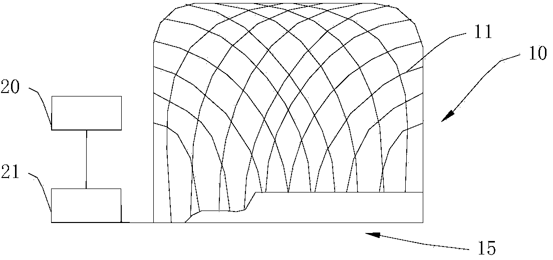
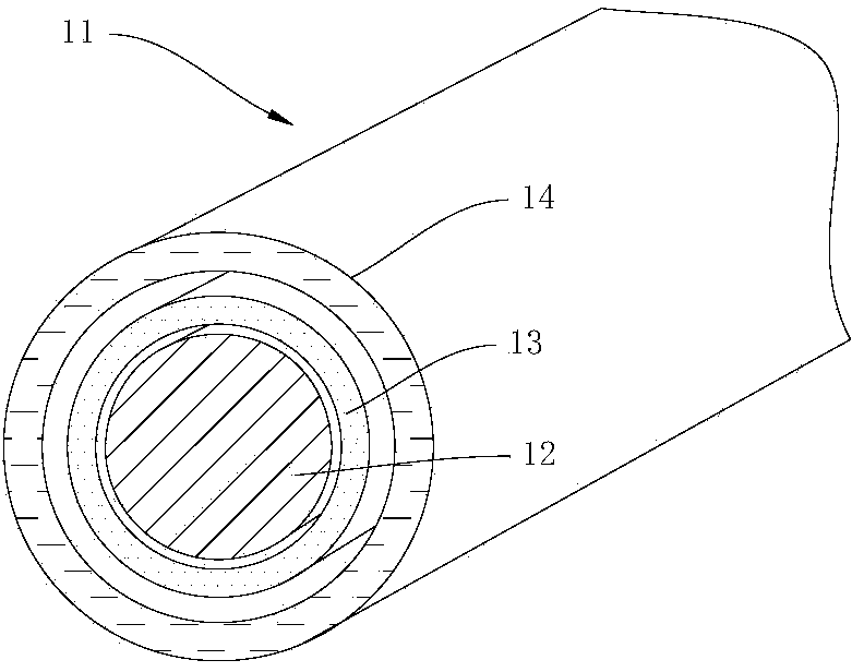
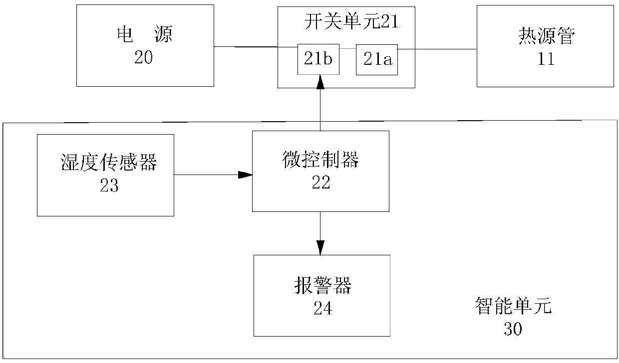
[0028] Such as figure 1 As shown, the hair drying cap of this embodiment has the basic function of drying hair, and it includes a cap body 10 which is formed by winding several heat source tubes 11. The heat source tube 11 is externally connected with a power source 20, and by being connected with the power source 20, the electric energy provided by the power source 20 is converted into heat energy at the heat source tube 11.

[0029] In order to control the heating temperature of the heat source tube 11 in time, a switch unit 21 is also provided in the circuit where the power source 20 and the heat source tube 11 are located. For example, it can be designed as a manual switch (not shown in the figure) to facilitate the user ...


PUM


Abstract

The invention relates to the technical field of hair drying appliances, in particular to a hair drying cap used for drying the hair. The hair drying cap comprises a cap body, wherein the cap body is formed by winding and lapping a plurality of heat source pipes; the heat source pipes give out heat after being connected with a power supply, comprise electric heating wires, insulating layers and water absorption layers from the inside out, and are mutually staggered to be reticular; an intelligent unit is further arranged on the outer side of an opening of the cap body of the hair drying cap. The hair drying cap has the advantages that on one hand, the heat source pipes are wound and lapped to form the cap body directly, so that the efficiencies of exchange and circulation of air inside and outside the hair drying cap can be improved, and the air permeability of the cap body can be increased, and on the other hand, due to the design of each heat source pipe, water in hair can be close to the heat source area to the maximum extent, then the evaporating temperature can be increased, and the water evaporation time can be shortened. After the intelligent unit is introduced, the heating time can be regulated and controlled according to the dryness condition of the hair.

Description

Technical field [0001] The invention relates to the field of hair dryers, in particular to a hair dryer cap capable of drying wet hair. Background technique [0002] In the prior art, the invention application with publication number CN102283489A discloses a quick-drying cap, which includes a semi-circular cap body, a brim connected with the cap body, an electric heating wire embedded in the cap body, and the electric heating wire passes The heating switch is connected to the power source. A cavity is arranged inside the cap body, and a fan is arranged in the cavity, and the fan is connected to the power supply through a heat dissipation switch. The above-mentioned quick-drying cap is heated by electric heating wire to dry the hair, and it is hoped that the fan will drive the air flow to achieve the purpose of evaporating the excess moisture of the hair. However, the cap body of the quick-drying cap has a closed structure, so that the air inside and outside the cap The exchange...

Claims


Application Information

Patent Timeline
Patent Type & Authority Applications(China)
IPC IPC(8): A45D20/24A45D20/30A45D20/38
Inventor 宁运琨王亚青赵国如李慧奇李梦华
Owner SHENZHEN INST OF ADVANCED TECH CHINESE ACAD OF SCI
Why Eureka
Try Eureka