Ground cleaning trolley

A ground cleaning and cleaning technology, which is applied in the field of cleaning vehicles, can solve the problems of cleaning vehicle residues, water cleaning traces that cannot be cleaned thoroughly, etc.

Inactive Publication Date: 2014-01-15
易良娟
View PDF2 Cites 15 Cited by
  • Summary
  • Abstract
  • Description
  • Claims
  • Application Information

AI Technical Summary

Problems solved by technology

[0003] The purpose of the present invention is to provide a cleaning vehicle suitable for cleaning floor tiles and floor materials, and to solve the problem that the residual water or cleaning marks cannot be thoroughly cleaned after the cleaning vehicle cleans the ground

Method used


Image

  • Ground cleaning trolley
  • Ground cleaning trolley
  • Ground cleaning trolley

Examples


Embodiment 1

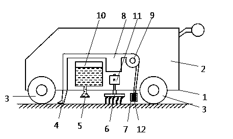
[0013] Such as figure 1 Shown, front and rear wheels are installed on the cleaning vehicle chassis 1, and front wheel 31 is steering wheel, and car body 2 is installed on the chassis 1. There is a push rod 21 at one end of the car body 2, and the cleaning personnel can hold and push the cleaning car ahead on this push rod when utilizing the cleaning car operation. The chassis 1 is provided with a dust collection port 4, a spray port 5, a cleaning mop 6 and a blowing port 7 in sequence. The dust collection port 4 is connected with the dust bag 8 through the pipeline, and the dust bag 8 is connected with the exhaust fan 9, and the air outlet of the exhaust fan 9 is connected with the air outlet 7 through the pipeline, and the electric heating wire 12 is arranged at the air outlet 7. When the cleaning vehicle is working, the suction fan 9 operates to form a pressure difference between the dust collection port 4 and the blowing port 7, and the air drives the ground dust to enter ...

Embodiment 2

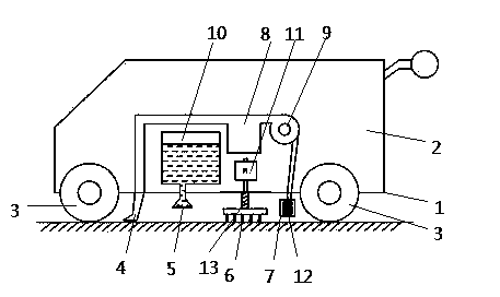
[0015] Such as figure 2 As shown, a spring 13 is provided between the cleaning mop 6 and the chassis 1, and the rest of the structure is the same as in Embodiment 1. This setting makes the cleaning mop 6 not only have the friction force generated by the rotation of the mop and the ground when the mop 6 rotates to wipe the ground, but also the downward pressure caused by the deformation of the spring 13, which simulates the manual wiping well. working condition, to achieve a better cleaning effect. When adding the liquid wax that floor waxing is useful in the water tank 10 in addition, this cleaning car can carry out floor waxing work.

Embodiment 3

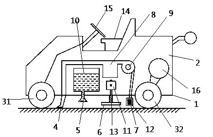
[0017] Such as image 3 As shown, the car body 2 is provided with a driver's seat 14 and a steering wheel 15, the steering wheel 15 is connected with the front wheel 31, and the car body 2 is also provided with a driving motor 16, and the driving motor 16 is connected with the rear wheel 32, and the cleaning vehicle All the other structures are the same as in Example 1. Utilize drive motor 16 to drive the advancement of the whole cleaning cart, and the cart cleaning mode of the cleaner is changed to driving mode, which is more time-saving and energy-saving when carrying out large-scale cleaning.


PUM


Abstract

The invention discloses a ground cleaning trolley which comprises a chassis, a trolley body and wheels. A dust collecting opening, a spraying opening, a cleaning mophead and an air blowing opening are sequentially formed in the chassis. A dust removal bag, an exhaust fan, a water tank and a motor are arranged inside the trolley body. The dust collecting opening is connected with the dust removal bag through a pipeline. The exhaust fan is connected behind the dust removal bag. An air outlet in the exhaust fan is connected with the air blowing opening through a pipeline. An electric heating wire is arranged at the position of the air blowing opening. The water tank is connected with the spraying opening. The motor is connected with the cleaning mophead. The cleaning trolley is applicable to leaning of the ground in floor tiles and wooden floors. After the cleaning work, the risk or floor deformation caused by the slippery ground generated by remaining water is prevented. After ground dust is collected through the dust collecting opening, water is sprayed through the spraying opening, the cleaning mophead connected with the motor rotates to conduct cleaning, strip-shaped cleaning marks are not easily reserved after working is completed, the ground is clean and tidy, and more time and labor are saved when the cleaning work is carried out by the cleaning trolley provided with a driving position.

Description

technical field [0001] The invention relates to a ground cleaning device, in particular to a cleaning vehicle for treating floors such as floor tiles and floors. Background technique [0002] Large supermarkets, department stores, indoor badminton courts, gymnasiums and other places are usually paved with floor tiles or wooden floors. These places have a large area, and manual cleaning with traditional tools such as brooms and mops is time-consuming and laborious, and cannot meet the increasingly high cleaning requirements of consumers. Therefore there have been some cleaning vehicles that replace manpower cleaning. As disclosed in CN202027520U "a new type of cleaning vehicle", the cleaning vehicle includes a vacuum cleaner and a mop that are close to the ground. There is a problem with manual cleaning, but after the mop cleans the floor with water, there is a lot of residual moisture on the floor, which makes the floor tiles slippery and easy to slip. There is a lot of m...

Claims


Application Information

Patent Timeline
Patent Type & Authority Applications(China)
IPC IPC(8): A47L11/26A47L11/40
Inventor 易良娟
Owner 易良娟
Why Eureka
Try Eureka