
Method for welding vacuum electron beam of stainless steel cylinder body

A technology of vacuum electron beam and stainless steel cylinder, applied in electron beam welding equipment, welding equipment, metal processing equipment and other directions, can solve the problems such as the inability to realize the overall processing of the cylinder body and the residual height difference on the back of the welding seam.

Inactive Publication Date: 2014-01-15
SHANGHAI XINLI POWER EQUIP RES INST
View PDF6 Cites 16 Cited by
  • Summary
  • Abstract
  • Description
  • Claims
  • Application Information

AI Technical Summary

Problems solved by technology

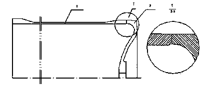
However, due to the limitation of the processing technology, it is impossible to realize the overall processing of the cylinder body. Therefore, under the premise of not affecting the performance of the cylinder body, the cylinder body is divided into two parts: the spinning cylinder body and the head, as shown in the attached figure 2 , and then the spinning cylinder and the head are assembled and welded by electron beam welding. After the weld seam passes the X-ray non-destructive inspection, it is mechanically cut and finished to the final dimensional accuracy of the cylinder.
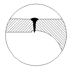
[0004] However if image 3 As shown, the back reinforcement of the weld formed by welding is out of tolerance

Method used


Image

  • Method for welding vacuum electron beam of stainless steel cylinder body
  • Method for welding vacuum electron beam of stainless steel cylinder body
  • Method for welding vacuum electron beam of stainless steel cylinder body

Examples


example

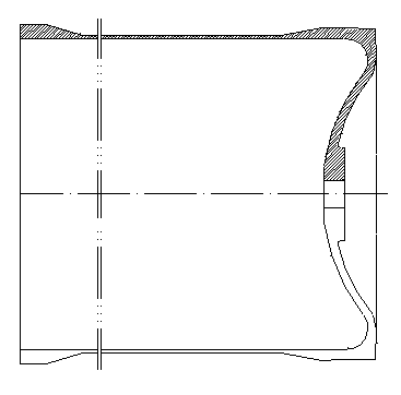
[0025] The present invention is implemented on a certain type of fuel tank cylinder, the outer diameter of the part to be welded is 212mm, the wall thickness of the cylinder to be welded is 6.45mm, the material grade is 00Cr19Ni11, and the structural form of the fuel tank cylinder is as attached figure 1 shown. The specific method is as follows:

[0026] Joint processing: welded joints are processed as attached figure 2 structure shown.

[0027] Cleaning of the parts to be welded on the shell: Grind the parts to be welded on the shell with sandpaper (the width is not less than 10mm), and polish to a metallic luster without scale and rust spots, and then clean the parts to be welded on the shell with absolute alcohol.

[0028] Assembling: Assemble the spinning cylinder and head to be welded together. The amount of misalignment is required to be ≤0.15mm, and the cylinder components are tightened and fixed with assembly tools, and the assembly gap at the butt joint is controll...


PUM


Abstract

The invention discloses a method for welding a vacuum electron beam of a stainless steel cylinder body. The method for welding the vacuum electron beam of the stainless steel cylinder body comprises the steps that the spinning cylinder body and an end socket are cleaned, a portion to be welded is polished, the width of the portion to be welded is no less than 10mm, the portion to be welded is polished until metallic luster appears, and the portion to be welded is cleaned; the spinning cylinder body and the end socket are assembled together in a butt joint mode, the alignment tolerance of the butt joint position is controlled to be smaller than or equal to 0.15mm, and the assembled assembly to be welded is clamped to a slewing device of an electron beam welding machine; the assembly to the welded is placed to a vacuum chamber, vacuumizing is conducted, and after the vacuum degree reaches 5*10<-4>mbar, vacuum electron beam welding is conducted on the cylinder body assembly through selected verified electron beam welding parameters; after electron beam welding is completed, the appearance quality of a welding seam is examined, and the objective that the surface of the welding seam is free of visible shortages is confirmed; after the tool is detached, the quality of the back face of the welding seam is examined and if welding leakage protruding out of the inner wall of the cylinder body does not exist, self-examination is qualified. The method is beneficial to the reliability and the stability of the quality of the product.

Description

technical field [0001] The invention relates to the field of welding technology, in particular to a vacuum electron beam welding method for a stainless steel cylinder. Background technique [0002] 00Cr19Ni11 is an austenitic stainless steel with a lower carbon content than 0Cr19Ni9. It has superior intergranular corrosion resistance and is a component that does not undergo heat treatment after welding. [0003] A fuel tank cylinder of a certain type uses the above-mentioned stainless steel as the raw material, and the design structure of the cylinder is as attached figure 1 The inner cavity of the cylinder is filled with some kind of fuel, and the movement of the fuel is realized by the one-way push of the piston along the inner wall of the cylinder, while the piston is guided by the guide ring. In order to ensure the utilization of fuel, the gap between the piston and the inner wall of the cylinder is required to be as small as possible to reduce the residual fuel due to ...

Claims


Application Information

Patent Timeline
IPC IPC(8): B23K15/00
CPCB23K15/06B23K15/002B23K15/0033B23K15/04
Inventor 潘丽华王勇沈慧萍
Owner SHANGHAI XINLI POWER EQUIP RES INST
Learn More