Molding method of hollow body with built-in component

A molding method and hollow body technology, which can be applied to hollow objects, other household appliances, household appliances, etc., can solve the problems of easy adhesion of blanks, easy leakage of hydrocarbons, unfavorable low evaporative emissions, etc., and achieve cost savings. , The way to reduce leakage, the effect of reducing the weight of the lower flash

Active Publication Date: 2014-01-15
YAPP AUTOMOTIVE PARTS
View PDF4 Cites 12 Cited by
  • Summary
  • Abstract
  • Description
  • Claims
  • Application Information

AI Technical Summary

Problems solved by technology

[0004] In order to obtain a larger space for the built-in components to pass through, there is a technical solution of cutting the cylindrical blank into two pieces in the prior art. After the built-in components are fixed, the two pieces of blanks are welded completely. Some problems encountered in the implementation of the equation, for example, the folds left by the cutting of the billet, the billet is easy to stick together, the welding place is still easy to leak hydrocarbons, etc.
In addition, in the conventional process, since the built-in component fixing device exits after the mold is closed, after the fuel tank body is obtained, a forming process hole is left in the fuel tank body, which needs subsequent welding and sealing, which increases the subsequent welding cost. , the production method of the existing technology is applied to the production of single-layer fuel tanks, but now most of the fuel tanks with built-in components are multi-layer fuel tanks
If the follow-up welding seal is continued, then the welding surface will increase the way for hydrocarbons to penetrate the fuel tank, which will easily cause environmental pollution, which is not conducive to meeting the requirements of OEMs and countries and regions on low evaporative emissions

Method used


Image

  • Molding method of hollow body with built-in component
  • Molding method of hollow body with built-in component
  • Molding method of hollow body with built-in component

Examples


Embodiment Construction

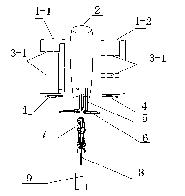
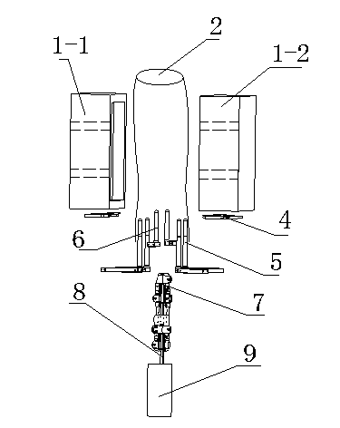
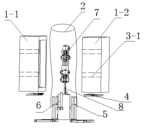
[0046] In order to deepen the understanding of the present invention, the present invention will be described in detail below in conjunction with the accompanying drawings; the hollow body in this embodiment refers to the oil tank.

[0047] see figure 1 , 2 :

[0048] First, install the built-in component with a manipulator on the built-in component fixing rod 8 at the lower end of the blank 2, the built-in component fixing rod 8 is fixed on the built-in component fixing device 9, the fixing rod 8 drops to the position and returns to the waiting position, and the four stretching rods 5 and The two expansion rods 6 are closed, and the distance between the four stretching rods and the two expansion rods is reduced as much as possible, so that the blank can be inserted into the stretching rod smoothly. When the stretching device is completely closed, the cylindrical The billet 2 is extruded from the upper end and descends slowly; the tubular billet is extruded and inserted i...


PUM


Abstract

The invention relates to a molding method of a hollow body with a built-in component. The method is characterized in that the method comprises the following steps: 1, arranging the built-in assembly on a built-in assembly fixing rod; 2, closing a tension device; 3, blanking, and allowing a cylindrical material base to be extruded from an upper end and slowly descend after the tension device is completely closed; 4, opening the tension device in the descending process of the material base to form an opening convenient for the pass of the built-in assembly; 5, ascending the built-in assembly to a final position after passing through the opening to complete the ascending process of the internal assembly; 6, pre-blowing a gas to the material base to complete a pre-blowing process; 7, allowing a die to be semi-closed; 8, taking the built-in assembly fixing rod out of the die mechanism; 9, fully closing the die; 10, blowing a high pressure gas to the material base to complete a gas blowing process; and 11, taking out the above obtained hollow body with the built-in component. The above technical scheme reduces the pollution to the environment, and protects the environment.

Description

technical field [0001] The invention relates to a method for forming a hollow body, in particular to a method with built-in components [0002] Hollow body molding method. Background technique [0003] There are many methods for forming hollow bodies in the prior art. Generally, the steps of hollow forming mostly go through the processes of stretching, clamping, pre-blowing and high-pressure blowing. With the development of new technologies and the strengthening of environmental protection regulations, relevant policies and laws and regulations have put forward more and more stringent environmental protection requirements for automobile OEMs, especially in terms of noise and evaporative emissions. Many internal integrated Parts, such as anti-wave boards, etc. The main function of anti-wave boards is to reduce noise. When the car is accelerating, braking or turning, the anti-wave boards can absorb the noise caused by fuel sloshing. This puts forward higher requirements for...

Claims


Application Information

Patent Timeline
Patent Type & Authority Applications(China)
IPC IPC(8): B29C49/04B29L22/00
CPCB29C2049/2078B29C49/20B29C49/4247B29C49/42B29C49/04
Inventor 高德俊李杰郭同杰翁益明宋庆华孙岩姜林徐松俊刘亮
Owner YAPP AUTOMOTIVE PARTS
Why Eureka
Try Eureka