Spiral type grain conveyor

A conveyor and screw technology, applied in the field of screw grain conveyors, can solve the problems of high cost, labor and time-consuming maintenance, complex production and processing structures of rollers and rollers, etc., and achieves safe and convenient use, low processing and production costs, and structural simple effect

Inactive Publication Date: 2014-01-15
杨可秀
View PDF8 Cites 6 Cited by
  • Summary
  • Abstract
  • Description
  • Claims
  • Application Information

AI Technical Summary

Problems solved by technology

[0002] At present, most of the conveyors used in the market are driven by rollers and rollers to support the rotation of the conveyor belt. The production and processing structure of rollers and rollers is complex, and maintenance is labor-intensive and costly.

Method used


Image

  • Spiral type grain conveyor

Examples


Embodiment Construction

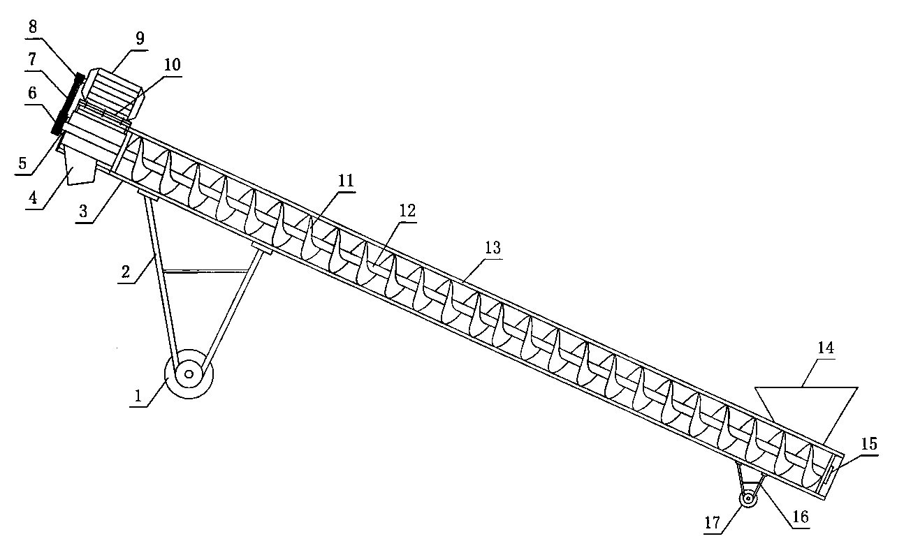
[0008] figure 1 The bottom side of frame 3 shown in is provided with front support 2, rear support 16, and the bottom end of front support is provided with front moving wheel 1, and the bottom end of rear support is equipped with rear moving wheel 17, and conveying circle is housed in the frame. Tube 13, the upper end of the frame is provided with an upper bearing seat 5, the lower end is equipped with a lower bearing seat 15, the upper and lower bearing seats are equipped with a screw shaft 12, the screw shaft is provided with a spiral blade 11, and the upper end of the screw shaft is equipped with a pulley 6, the machine The front upper end of the frame is provided with a motor support 10, a motor 9 is housed on the motor support, a motor pulley 8 is housed on the main shaft of the motor, a transmission belt 7 is housed on the motor pulley and the screw shaft pulley, and the lower end of the conveying cylinder is provided with a feed hopper 14, The upper end is provided with...


PUM


Abstract

The invention discloses a spiral type grain conveyor. A front support and a back support are arranged on the bottom side of a machine frame, a front moving wheel is arranged at the bottom end of the front support, a back moving wheel is arranged at the bottom end of the back support, a conveying roller for conveying grain is arranged inside the machine frame, an upper bearing base and a lower bearing base are arranged at the upper end of the machine frame, a spiral shaft is arranged in the upper bearing base and the lower bearing base, a spiral blade is arranged on the spiral shaft, the upper end of the spiral shaft is provided with a belt wheel, a motor support is arranged at the upper right end of the machine frame and is provided with a motor, a main shaft of the motor is provided with a motor belt wheel, a transmission belt is arranged on the motor belt wheel and the spiral shaft belt wheel, a feed hopper is arranged at the lower end of the conveying roller, and a discharge port is formed in the upper end of the conveying roller. In the process of working, the motor belt wheel drives the spiral shaft belt wheel to drive the spiral shaft to rotate, and the grain is discharged out of the discharge port through the spiral blade.

Description

technical field [0001] The invention relates to a grain conveying equipment, to be precise, a spiral grain conveying machine. Background technique [0002] At present, most of the conveyors used in the market are driven by rollers and rollers to support the rotation of the conveyor belt. The production and processing structures of rollers and rollers are complicated, and maintenance is labor-intensive, time-consuming, and costly. Contents of the invention [0003] The purpose of the present invention is to provide a screw type grain conveyor with simple structure, convenient maintenance and low production and processing costs. [0004] The scheme of the present invention is made up of frame, front and rear brackets, moving wheels, conveying cylinder, screw shaft, screw blade and motor. There are front moving wheels, rear moving wheels are installed at the bottom of the rear bracket, and a grain conveying cylinder is installed in the frame. The upper end of the frame is eq...

Claims


Application Information

Patent Timeline
Patent Type & Authority Applications(China)
IPC IPC(8): B65G33/14B65G41/00
Inventor 黄毅杨可秀
Owner 杨可秀
Why Eureka
Try Eureka