Special forklift used for aluminum ingot continuous casting production line

A casting production line, forklift technology, applied in the direction of lifting devices, etc., can solve the problems of large errors and difficult to guarantee accuracy, and achieve the effects of increasing costs, improving production efficiency and intelligence

Inactive Publication Date: 2014-01-15
LANZHOU UNIVERSITY OF TECHNOLOGY +1
0 Cites 5 Cited by

AI-Extracted Technical Summary

Problems solved by technology

This online automatic weighing method uses a set of pneumatic lifting device to lift the stack of aluminum ingots for weighing. It is a dynamic weighing method with large errors an...

Method used

As shown in FIG. 5 , the hydraulic station 70 and the oil tank 71 are instal...

Abstract

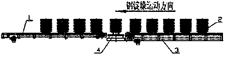
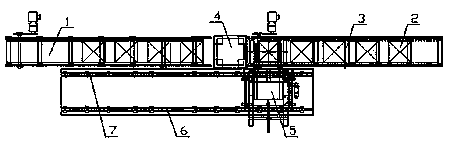
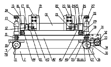
Disclosed is a special forklift used for an aluminum ingot continuous casting production line. An online dynamic weighing method of an existing aluminum ingot continuous casting production line is changed to an online static weighing method, and an existing automatic online weigher arranged inside a finished product conveyor is changed to an external automatic online weigher. A finished aluminum ingot stack (2) is conveyed to a transfer position through a primary finished product conveying machine (3), then the finished aluminum ingot stack (2) is transferred to an electronic balance (4) through the special forklift (5) to be weighed, after being weighed, the finished aluminum ingot stack (2) is transferred to a secondary finished product conveying machine (1) through the special forklift (5), and at last, the finished aluminum ingot stack (2) is conveyed to a finished product storehouse through the secondary finished product conveying machine (1). The special forklift (5) returns to the original position to repeat a next cycle.

Application Domain

Technology Topic

Image

  • Special forklift used for aluminum ingot continuous casting production line
  • Special forklift used for aluminum ingot continuous casting production line
  • Special forklift used for aluminum ingot continuous casting production line

Examples

  • Experimental program(1)

Example Embodiment

Such as figure 1 , figure 2 As shown, the present invention changes the online dynamic weighing method of the existing aluminum ingot continuous casting production line into an online static weighing method, and changes the existing online automatic scale built in the finished product conveyor into an external online automatic scale. That is to say, the original structure becomes an online static weighing system composed of a first-level finished product conveyor 3, an electronic scale 4, a special forklift 5 and a second-stage finished product conveyor 1. The working principle is: the finished aluminum ingot stack (2) is transported by the first-level finished product conveyor 3 to the transfer position, and then transferred by the special forklift 5 to the electronic scale 4 for weighing, and then transferred by the special forklift 5 to the second level after weighing On the finished product conveyor 1, finally the aluminum ingot stack 2 is transported by the secondary finished product conveyor 1 to the finished product warehouse. The special forklift 5 returns to the initial position and repeats the next cycle. In this way, the online static weighing of the aluminum ingot stack 2 is realized, and the efficiency of the entire aluminum ingot continuous casting production line is improved.
Such as figure 1 , figure 2 As shown, the special forklift used for the continuous casting production line of aluminum ingots, the electronic scale 4 is installed between the first level finished product conveyor 3 and the second level finished product conveyor 1, and the first track 6 and the second track 7 of the special forklift 5 are installed in the production line One side; such as image 3 , Figure 4 , Figure 5 As shown, the dedicated forklift 5 is composed of a translational vehicle body 42, a forklift frame 74 and a forklift body 20. Such as Figure 4 As shown, the translation vehicle body 42 is formed by welding a first rectangular tube 67, a second rectangular tube 68, a third rectangular tube 72, and a third rectangular tube 73. The first UCP bearing 10 and the second UCP bearing 48 are installed below the third rectangular tube 73. The driven axle 8 is connected to the translational vehicle body 42 through the first UCP bearing 10 and the second UCP bearing 48. A first wheel 9 and a second wheel 75 are fixedly connected to both ends of the driven axle 8; a third UCP bearing 40 and a fourth UCP bearing 58 are installed below the third rectangular tube 72. The driving axle 37 is connected to the translation vehicle body 42 through the third UCP bearing 40 and the fourth UCP bearing 58. A third wheel 38 and a fourth wheel 66 are fixedly connected to both ends of the driving axle 37.
Such as Figure 4 , Figure 5 As shown, the forklift frame 74 is formed by welding the fifth rectangular tube 16, the sixth rectangular tube 25, the first cross beam 52, the second cross beam 65, and the third cross beam 62. The first rail 17 and the second rail 41 are U-shaped, and are welded to the inner side of the fifth rectangular tube 16 and the sixth rectangular tube 25, respectively. The first lug 15 and the second lug 26 are L-shaped, and are welded to the front ends of the fifth rectangular tube 16 and the sixth rectangular tube 25, respectively. The tail of the first lifting cylinder 13 is connected to the translation vehicle body 42 through a first hinge 11; the tail of the second lifting cylinder 28 is connected to the translation vehicle body 42 through a second hinge 39. The piston rod of the first lifting cylinder 13 is hinged with one end of the first lug 15 through the first pin 14 and the piston rod of the second lifting cylinder 28 is hinged with one end of the second lug 26 through the second pin 27; The forklift frame 74 is hinged with the translation vehicle body 42 through the third hinge 29 and the fourth hinge 44.
Such as image 3 , Figure 4 , Figure 5 As shown, the upper end surfaces of the first leg 45 and the second leg 61 are welded to the lower surfaces of the fifth rectangular tube 16 and the sixth rectangular tube 25, respectively. In the free state, the lower end surfaces of the first leg 45 and the second leg 61 fall on the upper surface of the first rectangular tube 67 of the translation vehicle body 42 to play a supporting role.
Such as image 3 , Figure 4 As shown, the forklift body 20 is formed by welding a seventh rectangular tube 51, an eighth rectangular tube 55, a ninth rectangular tube 56 and a tenth rectangular tube 59. The roller 12, the roller 50, the roller 24 and the roller 57 are respectively mounted on one end of the shaft 43, the shaft 77, the shaft 21 and the shaft 76, and a rolling bearing is installed between the roller and the shaft. The shaft 43 and the shaft 77 are fixed on the outside of the seventh rectangular tube 51; the shaft 21 and the shaft 76 are fixed on the outside of the ninth rectangular tube 56. The roller 12 and the roller 50 roll in the first guide rail 17; the roller 24 and the roller 57 roll in the second guide rail 41.
Such as image 3 As shown, the first connecting plate 19 and the second connecting plate 22 have the same structure, the upper half has two parallel long circular holes, and the lower half is welded to the outside of the tenth rectangular tube 59 of the forklift body 20. The first forklift arm 18 and the second forklift arm 23 are respectively connected to the first connecting plate 19 and the second connecting plate 22 through a bolt group. Since the first connecting plate 19 and the second connecting plate 22 are designed with long round holes, the distance between the first forklift arm 18 and the second forklift arm 23 can be adjusted according to the size of the aluminum ingot stack.
Such as Figure 4 , Figure 5 As shown, the cylinder body of the translation cylinder 54 is hinged on the first cross beam 52 of the forklift frame 74 through a hinge 53. The support 64 is welded to the inner side of the tenth rectangular tube 59 of the forklift body 20. The support 64 is hinged with the end of the piston rod of the translation cylinder 54 through a pin 63.
Such as Figure 4 As shown, the connecting plate 31 is fixed on the outer side of the third rectangular tube 72 of the translation vehicle body 42 and is designed with an elongated circular hole. The servo motor 32 is fixed to the connecting plate 31 by a bolt group. The adjusting device 30 is fixed on the upper surface of the third rectangular tube 72 of the translation vehicle body 42.
Such as image 3 , Figure 4 , Figure 5 As shown, the driving sprocket 34 is fixed on the output shaft of the servo motor 32 by keys, and the driven sprocket 36 is fixed on the driving axle 37 by keys. Transmission between the driving sprocket 34 and the driven sprocket 36 is realized by a chain 35.
Such as Figure 4 , Figure 5 As shown, the bracket 47 is welded on the fourth rectangular tube 73 of the translation vehicle body 42 and is perpendicular to the fourth rectangular tube 73. A photoelectric switch 46 and a photoelectric switch 69 are mounted on the bracket 47 to control the highest and lowest limit positions of the forklift body 20. The photoelectric switch 49 and the photoelectric switch 60 are installed on the fifth rectangular tube 16 of the forklift frame 74 to control the extension and retraction limit position of the forklift body 20.
Such as Figure 5 As shown, the hydraulic station 70 and the fuel tank 71 are installed on the forklift body 20, and play a role of counterweight while saving space.
The working process of the present invention is as follows: figure 1 , figure 2 As shown, in the initial state, the special forklift 5 is at the right extreme position, that is, at the leftmost aluminum ingot stacking position of the first-level finished product conveyor 3. Such as image 3 , Figure 4 , Figure 5 As shown, when the aluminum ingot stack 2 reaches the leftmost stack position of the first-level product conveyor 3, the system PLC controls the first-level product conveyor 3 to stop, the translation cylinder 54 extends, and drives the forklift body 20 to move forward to make the first The forklift arm 18 and the second forklift arm 23 extend directly below the aluminum ingot stack 2, and then the first lifting cylinder 13 and the second lifting cylinder 28 rise, driving the forklift frame 74 and the forklift body 20 around the third hinge 29 and The fourth hinge 44 rotates, so that the aluminum ingot stack 2 is separated from the leftmost stack position of the first-level finished product conveyor 3 and rises to the highest limit position. Next, the translation cylinder 54 retracts, driving the forklift body 20 and the aluminum ingot stack 2 to move back to the initial position, the first lifting cylinder 13 and the second lifting cylinder 28 descend, the first leg 45 and the second leg 61 The lower end surface of the aluminum plate falls on the upper surface of the first rectangular tube 67 of the translational vehicle body 42, and supports the weight of the aluminum ingot stack 2. After that, the system PLC controls the action of the servo motor 32 to drive the special forklift 5 and the aluminum ingot stack 2 to move to the left along the first track 6 and the second track 7 to the weighing position. The first lifting cylinder 13 and the second lifting cylinder 28 rise, the lower end surfaces of the first leg 45 and the second leg 61 are separated from the upper surface of the first rectangular tube 67 of the translation vehicle body 42, and the translation cylinder 54 extends The aluminum ingot stack 2 moves directly above the electronic scale 4, the first lifting cylinder 13 and the second lifting cylinder 28 descend, and the aluminum ingot stack 2 is placed on the electronic scale 4 smoothly. After the weighing is completed, the first lifting cylinder 13 and the second lifting cylinder 28 rise, so that the aluminum ingot stack 2 separates from the electronic scale 4, the translation cylinder 54 retracts, and the first lifting cylinder 13 and the second lifting cylinder 28 descends, and the lower end surfaces of the first leg 45 and the second leg 61 fall on the upper surface of the first rectangular tube 67 of the translation vehicle body 42. The system PLC controls the action of the servo motor 32, driving the special forklift 5 and the aluminum ingot stack 2 to continue to move to the left, reaching the rightmost stack position of the secondary product conveyor 1, and the first lifting cylinder 13 and the second lifting cylinder 28 rise After the translation cylinder 54 extends to move the aluminum ingot stack 2 directly above the rightmost stack position of the secondary product conveyor 1, the first lifting cylinder 13 and the second lifting cylinder 28 descend to place the aluminum ingot stack 2 on At the rightmost stack position of the secondary product conveyor 1, the translation cylinder 54 is retracted. Then the system PLC controls the secondary finished product conveyor 1 to move one stack to the left and then stops, while the servo motor 32 drives the special forklift 5 to the initial position, ready to transfer the next stack of aluminum ingots.

PUM

no PUM

Description & Claims & Application Information

We can also present the details of the Description, Claims and Application information to help users get a comprehensive understanding of the technical details of the patent, such as background art, summary of invention, brief description of drawings, description of embodiments, and other original content. On the other hand, users can also determine the specific scope of protection of the technology through the list of claims; as well as understand the changes in the life cycle of the technology with the presentation of the patent timeline. Login to view more.

Similar technology patents

Classification and recommendation of technical efficacy words

Why Eureka
Try Eureka