Electrolytic bath cathode steel bar connecting plate structure

A technology of cathode steel rod and connecting plate, applied in the field of component connection structure, can solve the problems of small welding connection area and unreliable connection, etc.

Inactive Publication Date: 2014-01-15
GUIYANG AL-MG DESIGN & RES INST
View PDF6 Cites 1 Cited by
  • Summary
  • Abstract
  • Description
  • Claims
  • Application Information

AI Technical Summary

Problems solved by technology

The connection plate with rectangular structure has the disadvantages of small welding connection area and unreliable connection.

Method used


Image

  • Electrolytic bath cathode steel bar connecting plate structure
  • Electrolytic bath cathode steel bar connecting plate structure
  • Electrolytic bath cathode steel bar connecting plate structure

Examples


Embodiment 1

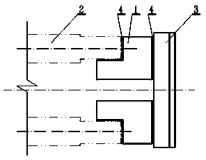
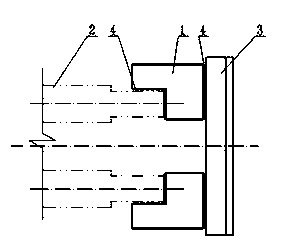
[0021] "L" shaped connecting plate 1 is to increase the welding contact area with the end face and side of the cathode steel rod 2; "L" shaped connecting plate 1 can be placed on the inner surface of the cathode steel rod 2, such as figure 1 , can also be placed on the outer side of the cathode steel rod 2, such as figure 2 .

Embodiment 2

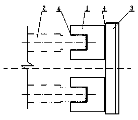
[0023] Two "L"-shaped connecting plates 1 form a "concave"-shaped connecting plate to increase the welding contact area with the end face and both sides of the cathode steel rod 2, such as image 3 . The figure shows that two "concave"-shaped connecting plates connect two cathode steel rods at the same time;

Embodiment 3

[0025] Two "L"-shaped connecting plates 1 form a "convex"-shaped connecting plate, which simultaneously connects the left and right cathode steel rods 2 and the steel-aluminum explosion welding block 3, such as Figure 4 , the weld between the connecting plate and the cathode steel rod is located on the inner surface and end surface of the cathode steel rod;

[0026] Such as Figure 5 , Two "L"-shaped connecting plates form a "concave"-shaped connecting plate, which connects the end faces, outer faces and steel-aluminum explosive welding blocks of two cathode steel rods at the same time.


PUM


Abstract

The invention discloses an electrolytic bath cathode steel bar connecting plate structure, which adopts ''L'' shaped connecting plates (1). The ''L'' shaped connecting plates (1) connect cathode steel bars with a steel-aluminum explosive welding block (3) through a welding seam (4). The ''L'' shaped connecting plates (1) are placed on the inner sides of the cathode steel bars (2), or on the outer sides of the cathode steel bars (2). The two ''L'' shaped connecting plates (1) form a ''concave'' structure connecting plate, or form a ''convex'' structure connecting plate. The ''concave'' structure connecting plate or the ''convex'' structure connecting plate composed of the ''L'' shaped connecting plates (1) connects the two cathode steel bars (2) simultaneously. By welding the ''L'' shaped connecting plates with the end faces and the sides of the cathode steel bars, the welding seam can be elongated, and the welding contact area can be increased, thereby reaching the purpose of lowering the electrolytic bath cathode drop.

Description

technical field [0001] The invention relates to a part connection structure of a cathode steel bar head of an aluminum electrolytic cell. Background technique [0002] There are generally two methods of connection between the cathode steel rod and the cathode soft belt of the electrolytic cell: welding and crimping. In recent years, the design basically adopts the crimping method, but the early large-scale prebaked anode electrolytic cells at home and abroad all adopt the welding method. Compared with the crimping method, the cathode steel rod and the explosive welding block are connected through the connection plate, which has the characteristics of good connection effect, low pressure drop, low heat and power consumption, and energy saving. [0003] On the existing electrolytic cell, the connecting plate is usually rectangular, one side is welded with the end face of the cathode steel rod, and the other side is welded with the explosive welding block to achieve the purpose...

Claims


Application Information

Patent Timeline
Patent Type & Authority Applications(China)
IPC IPC(8): C25C3/08
Inventor 黄俊杨涛王紫千
Owner GUIYANG AL-MG DESIGN & RES INST
Why Eureka
Try Eureka