Load self-adaptation gas-fired device of gas engine

A gas engine and gas device technology, applied to combustion engines, internal combustion piston engines, engine components, etc., can solve problems such as poor energy saving effect and complex structure

Active Publication Date: 2014-01-15
重庆金之川动力机械有限公司
View PDF7 Cites 1 Cited by
  • Summary
  • Abstract
  • Description
  • Claims
  • Application Information

AI Technical Summary

Problems solved by technology

The invention has high working stability (keep the speed constant when the load changes) and can increase the output power of the engine by 10-20%. At the same time, it sol

Method used


Image

  • Load self-adaptation gas-fired device of gas engine
  • Load self-adaptation gas-fired device of gas engine
  • Load self-adaptation gas-fired device of gas engine

Examples


Embodiment 1

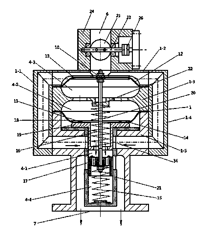
[0031] Such as figure 1 , 2 , 3: a gas engine load self-adaptive gas device, including a casing 1 with an accommodating cavity

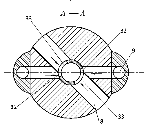
[0032](combined and fixed by five parts 1-1, 1-2, 1-3, 1-4, 1-5) and the air chamber 2, gas chamber 3 and gas mixing chamber arranged in the cavity Chamber 4, air inlet 5, gas inlet 6 and mixed gas outlet 7 are arranged on the shell, air channel 8 and gas channel 9 are formed between the inner surface of the shell and the walls of air chamber 2 and gas chamber 3 respectively, and also includes The upper diaphragm assembly 10, the lower diaphragm assembly 11, the upper diaphragm assembly 10 separates the gas chamber 3 and the gas mixing chamber 4, the lower diaphragm assembly 11 separates the air chamber 2 and the gas mixing chamber 4, and the gas mixing chamber There is a perforated partition 22 extending from the shell between the upper and lower diaphragms;

[0033] The upper diaphragm assembly 10 includes an upper diaphragm 12 , two symmetrica...

Embodiment 2

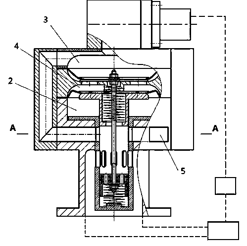
[0046] Such as figure 2 , 3 Shown in , 4: different from embodiment 1: also comprise electronic speed control controller 29, the signal input end of electronic speed control controller 29 connects the speed sensor 30 on the engine 28, and the control output end connects throttle valve 25 places The executive motor 27 and the electronic speed control controller 29 compare the rotational speed parameters collected by the speed measuring sensor 30 with the internally set rotational speed parameters, and intelligently adjust the intake of gas according to the comparison results. For example: when the rotational speed of the engine 28 is lower than the set value (after parameter comparison), the electronic speed control controller 29 outputs the "increase" drive pulse to the actuator motor 27, and the actuator motor 27 rotates the throttle to "increase" the throttle. The direction of the opening of the valve 25 is rotated to ensure that the increased gas enters the gas chamber 3,...

Embodiment 3

[0048] Such as Figure 5 As shown: the difference from Embodiment 1 and 2 is that the piston sleeve 21 is provided with a rotating rod 31 that can be rotated, and pushing the rotating rod 31 can change the ratio of the cross-sectional area of ​​the air and gas passing through the air inlet hole on the piston sleeve 21, Then it can adjust the intake volume of air and gas, and adjust the mixing ratio of air and gas in rough steps.

[0049] The diaphragms described in the above three embodiments are made of elastic soft materials, so that they are more sensitive when sensing pressure changes.


PUM


Abstract

The invention discloses a load self-adaptation gas-fired device of a gas engine. The load self-adaptation gas-fired device of the gas engine comprises an air channel, an air inlet, a gas channel, a gas inlet, a mixed gas channel, a mixed gas outlet, an upper diaphragm assembly, a lower diaphragm assembly, a gas chamber, a mixed gas chamber and an air chamber, wherein the gas chamber and the mixed gas chamber are separated by the upper diaphragm assembly, the air chamber and the mixed gas chamber are separated by the lower diaphragm assembly, the upper diaphragm assembly and a lower piston are fixedly connected into a whole through an adjusting threaded rod, the lower diaphragm assembly and an upper piston are fixedly connected into a whole through a pressure plate, metering holes are formed in a piston sleeve, and are used for input of air and gas and output of mixed gas, the metering holes are in a plugged or an open state along with movement of a piston head, and the upper diaphragm assembly and the lower diaphragm assembly can move vertically along with changes of air pressure, and drive the upper piston and the lower piston to move perpendicularly, so that the size of the air metering hole and the size of the gas metering hole are changed. The load self-adaptation gas-fired device of the gas engine can automatically provide the mixed gas with the appropriate amount according to the requirement of the gas engine, and can also automatically adjust the concentration of the mixed gas according to the requirement of load changes so that the purpose of improving power performance of the gas engine and the purpose of saving energy can be achieved.

Description

technical field [0001] The invention belongs to the technical field of gas engines, and in particular relates to a gas engine load adaptive gas device. Background technique [0002] The traditional engine gas device is generally composed of a pressure reducing regulator and a mixer (venturi or proportional type). This kind of gas device can mix the gas with stable pressure with air in a relatively accurate proportion after being decompressed and stabilized. The gas concentration remains basically unchanged, which can provide a relatively stable mixture for the engine. The problems of these gas devices are: 1. The mixed gas cannot be provided according to the intake demand of the engine, and the direct result is that the efficiency of the mixed gas combustion is reduced; 2. When the intake gas source is unstable, the device cannot automatically adjust the gas supply and The intake air mixture ratio, the direct result is vibration or dead fire shutdown; 3. For unclean, dusty ...

Claims


Application Information

Patent Timeline
IPC IPC(8): F02M21/04
CPCY02T10/30
Inventor 杨少波王秋勇
Owner 重庆金之川动力机械有限公司
Why Eureka
Try Eureka