High-pressure intermediate-stage guide blade of gas compressor for combustion gas turbine

A technology of gas turbines and compressors, which is applied in the direction of machines/engines, liquid fuel engines, components of pumping devices for elastic fluids, etc. It can solve problems such as low work efficiency, affecting the safe operation of compressors, and short service life. It achieves the effect of prolonging the service life, facilitating the axial installation into the wheel groove and increasing the stability

Inactive Publication Date: 2014-01-15
HARBIN TURBINE
View PDF6 Cites 2 Cited by
  • Summary
  • Abstract
  • Description
  • Claims
  • Application Information

AI Technical Summary

Problems solved by technology

[0003] In order to solve the problems of low working efficiency, short service life and influence on the safe operation of the compressor high-pressure intermediate guide vane used in the existing gas turbine, the present invention further proposes a high-pressure intermediate guide vane for the gas turbine compressor

Method used


Image

  • High-pressure intermediate-stage guide blade of gas compressor for combustion gas turbine
  • High-pressure intermediate-stage guide blade of gas compressor for combustion gas turbine
  • High-pressure intermediate-stage guide blade of gas compressor for combustion gas turbine

Examples


specific Embodiment approach 1

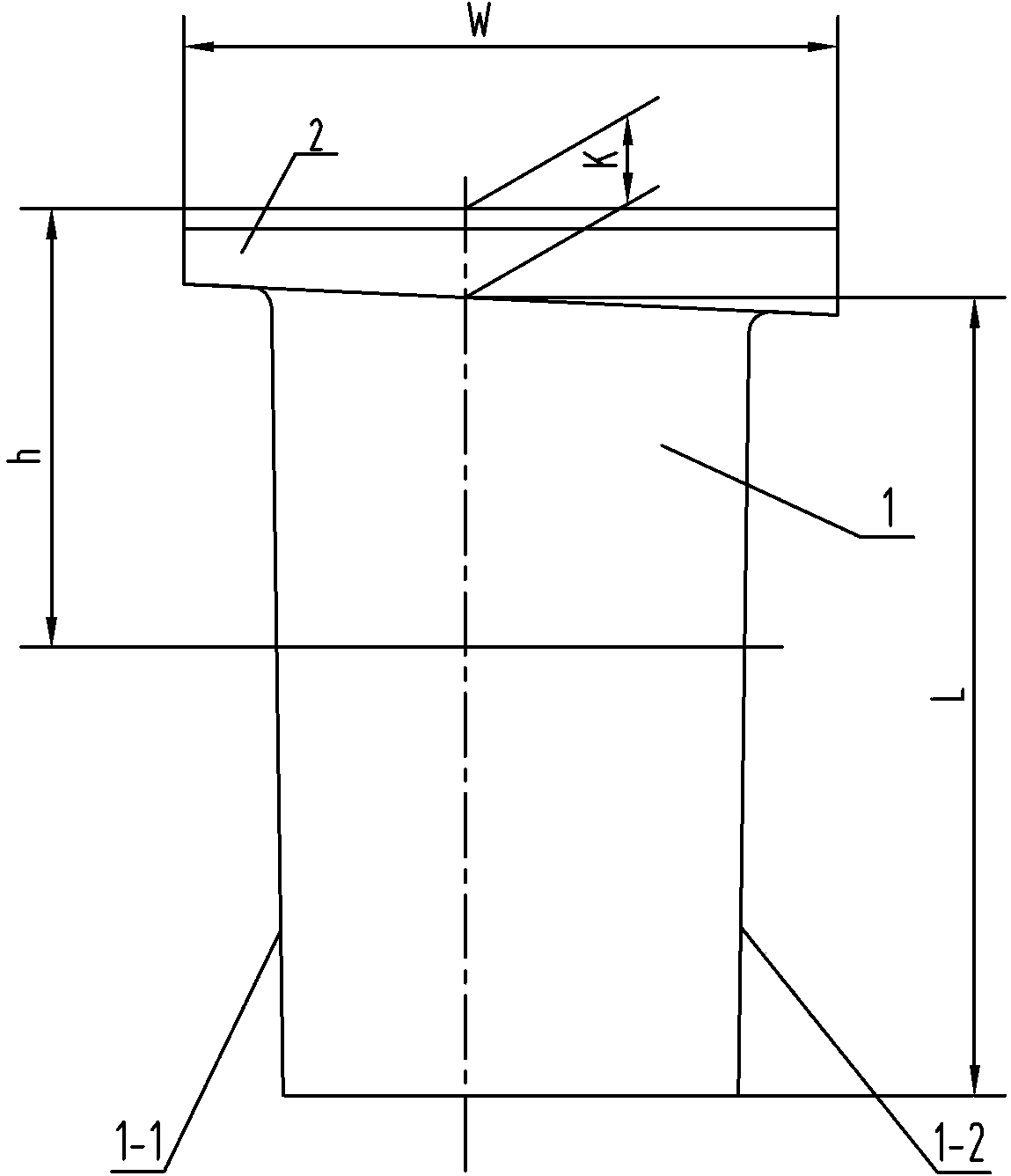
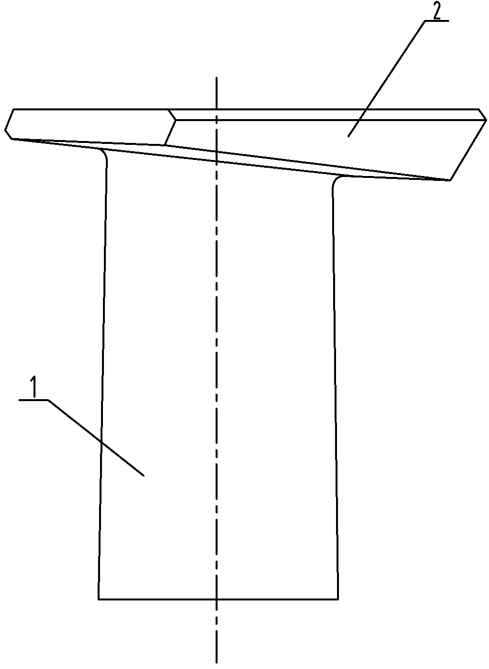
[0007] Specific implementation mode one: as Figure 1-2 As shown, the high-pressure intermediate guide vane of a gas turbine compressor in this embodiment includes a blade working area 1 and a blade root 2, and the blade working area 1 and blade root 2 are integrated from top to bottom, and the blade working area 1 One side of the blade is the air inlet side 1-1, and the other side of the blade working area 1 is the air outlet side 1-2. The blade working area 1 is a twisted blade with equal cross-section. reduced, there is a relative twist between two adjacent sections, and the blade root 2 is a dovetail-shaped blade root. Designed in this way, this structure enables the blade to be firmly installed into the wheel rim, and is convenient to be axially installed into the wheel groove, with a large bearing area, safety and reliability.

specific Embodiment approach 2

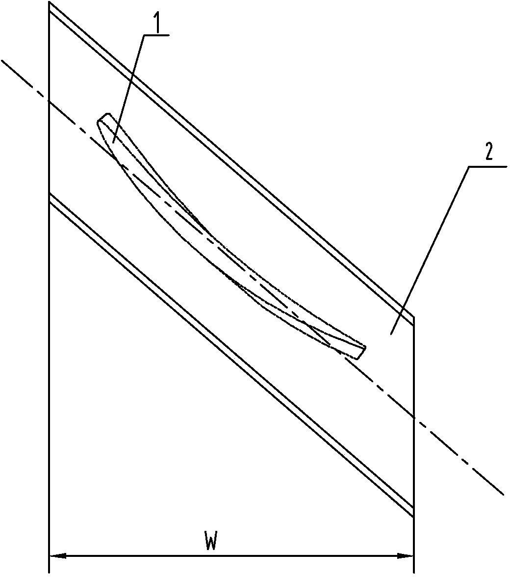
[0008] Specific implementation mode two: as Figure 1-6 As shown, the section height of the blade working area 1 in this embodiment is h, the chord length is b, the installation angle is β, the maximum profile thickness is δ, the total height of the blade working area 1 is L, and the distance from the air outlet edge is The thickness of the air outlet edge at L1 is D1, the height of the blade root 2 is k, and the width of the blade root 2 is W. Other compositions and connections are the same as in the first embodiment.

specific Embodiment approach 3

[0009] Specific implementation mode three: as Figure 1-6 As shown, the section height of the blade working area 1 in this embodiment from the root to the top is h9.50mm-48.50mm, the chord length b is 31.21mm, the installation angle β is 48.67-45.65°, and the maximum thickness δ of the profile line is 1.87mm, the total height L of the blade working area 1 is 39.60mm, the thickness D1 of the air outlet edge at the distance L1 from the air outlet edge is 1mm is 0.39mm, the height k of the blade root 2 is 4.40mm, and the width W of the blade root 2 is 32.50mm. By adopting the above structural parameters, the blades can be easily assembled while ensuring that the outer structure dimensions of the blades meet the design requirements. Other compositions and connections are the same as those in the second embodiment.


PUM


Abstract

The invention belongs to a gas compressor blade, and particularly relates to a high-pressure intermediate-stage guide blade of a gas compressor for a combustion gas turbine. The high-pressure intermediate-stage guide blade of the gas compressor for the combustion gas turbine resolves the problems that an existing high-pressure intermediate-stage guide blade of a gas compressor for a combustion gas turbine is low in working efficiency and short in service life and affects safe operation of the gas compressor. The high-pressure intermediate-stage guide blade of the gas compressor for the combustion gas turbine comprises a blade working area (1) and a blade root (2), wherein the blade working area (1) and the blade root (2) are manufactured integrally from top to bottom, one side of the blade working area (1) is a gas inlet side (1-1), the other side of the blade working area (1) is a gas outlet side (1-2), the blade working area (1) is a uniform-section twisted blade, shapes of sections along the height of the blade are the same, installation angles of all section model lines are gradually reduced, relative twisting exists between two adjacent sections, and the blade root (2) is a forked tail type blade root. The high-pressure intermediate-stage guide blade is mainly used for the gas compressor for the combustion gas turbine.

Description

technical field [0001] A compressor blade, and the invention specifically relates to a high-pressure intermediate-stage guide blade of a gas turbine compressor. Background technique [0002] At present, the high-pressure intermediate-stage guide blades of gas turbines used in gas turbines have a single variety, primitive design methods, low calculation accuracy, and cannot perform accurate aerodynamic calculations and flow field calculations, resulting in uneven blade profile design, low work efficiency, and short service life. , has seriously affected the safe operation of the compressor. Contents of the invention [0003] In order to solve the problems of low working efficiency, short service life and influence on the safe operation of the compressor high-pressure intermediate guide vane used in the existing gas turbine, the present invention further proposes a high-pressure intermediate guide vane for the gas turbine compressor. [0004] The technical solution adopted ...

Claims


Application Information

Patent Timeline
Patent Type & Authority Applications(China)
IPC IPC(8): F04D29/38
Inventor 张秋鸿张宏涛梁培培冯永志张巍刘强史秋张春梅
Owner HARBIN TURBINE
Why Eureka
Try Eureka