
Energy storage type parking unit brake cylinder

A unit brake cylinder and parking brake technology, which is applied in the direction of brake actuators, gear transmission mechanisms, mechanical equipment, etc., can solve the problems of parking cylinders that cannot be inflated, inconvenient installation, loss of function, etc., to achieve reliability and safety High, small footprint, compact structure effect

Active Publication Date: 2014-01-15
CRRC QISHUYAN INSTITUTE CO LTD +1
View PDF4 Cites 27 Cited by
  • Summary
  • Abstract
  • Description
  • Claims
  • Application Information

AI Technical Summary

Problems solved by technology

The existing energy-storage brake cylinders are all independent, and the disadvantage is that there must be an independent unit brake cylinder and an independent parking brake cylinder, so the volume is large and the installation is inconvenient
Moreover, the parking piston of the existing energy storage parking brake cylinder is directly installed on the hand brake sleeve through a non-self-locking thread, and the release pull pin must always be pulled out of the tooth groove of the hand brake sleeve during relief.
The release pull pin must also be pulled out when the parking cylinder is inflated after manual release, otherwise the parking cylinder cannot be inflated, and the parking piston cannot reach the correct position to compress the parking spring to store energy, thus losing its proper function

Method used


Image

  • Energy storage type parking unit brake cylinder
  • Energy storage type parking unit brake cylinder
  • Energy storage type parking unit brake cylinder

Examples


Embodiment Construction

[0035] The present invention is described in further detail below in conjunction with the embodiment that accompanying drawing provides.

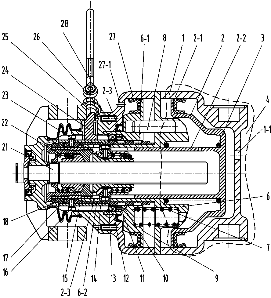
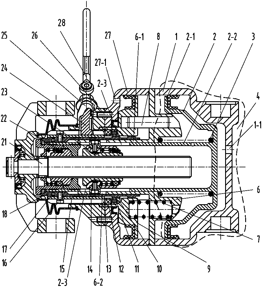
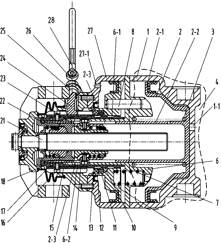
[0036] like Figure 1~12As shown, an energy storage type parking unit brake cylinder of the present invention includes two parts, a unit brake cylinder part and a parking brake cylinder part, and the unit brake cylinder part includes a brake cylinder 4, a reset mechanism 21 and a gap Adjusting mechanism, the brake cylinder 4 includes a brake cylinder 1 provided with a first air inlet 1-1 and a brake piston 2 arranged in the brake cylinder 1, and the brake piston 2 includes a The piston body 2-1 fitted on the inner wall of the moving cylinder body 1 and the piston tube 2-2 extending from the middle of the piston body 2-1 to one side; one end of the brake cylinder body 1 is fixedly connected with an intermediate body 6, and the intermediate body 6 A relief spring 3 is provided between the piston body 2-1 of the brake piston 2; The inner wal...


PUM


Abstract

The invention discloses an energy storage type parking unit brake cylinder. The energy storage type parking unit brake cylinder comprises a unit brake cylinder and a parking brake cylinder, a brake piston comprises a piston body and a piston pipe, the piston body is matched with the inner wall of a brake cylinder block, one end of the brake cylinder block is fixedly connected with a middle body, a buffering spring is arranged between the middle body and the brake piston, and the periphery of the piston pipe is in sliding fit with the inner wall of a central pipe of the middle body. The piston pipe is composed of a regulating nut and a guide nut in a connected mode, a reset mechanism is composed of a screw, a yoke and the like, and the screw is connected with the regulating nut and the guide nut through non-self-locking nuts. The parking brake cylinder comprises a parking cylinder block, a parking piston, a parking regulating nut, a parking spring, a guide pin, a gear ring, a hand brake sleeve, a ball assembly, a pushing ring, a piston pipe cover and a manual-operation buffering device, wherein the parking cylinder block is provided with a second air inlet, and one end of the parking cylinder block is fixedly connected with the middle body. The energy storage type parking unit brake cylinder integrates the parking brake cylinder and the unit brake cylinder, and is compact in structure, small in size and convenient to install.

Description

[0001] technical field [0002] The invention relates to a braking device of a rail transit vehicle, in particular to a unit brake cylinder capable of realizing the parking brake function for the rail transit vehicle. Background technique [0003] Air brakes are now widely used in rail transit vehicles, and the brake cylinder is a device that transmits the air pressure of the vehicle's main air duct to the basic braking part, so that the vehicle can perform service braking from motion to rest. Due to the inevitable leakage of the air brake, it is impossible to keep the railway locomotive parked on the line or in the warehouse for a long time. Rail transit vehicles not only require a service braking function, but also a parking braking function. [0004] The parking brake of rail transit can be roughly divided into two categories according to the principle of action: 1. Hand brake: The hand brake is driven by rotating a manual control disc, driven by the sprocket chain, pull...

Claims


Application Information

Patent Timeline
Patent Type & Authority Applications(China)
IPC IPC(8): F16D65/14F16D121/04F16D125/02
Inventor 张勋林钱坤才郑剑云陈炳伟
Owner CRRC QISHUYAN INSTITUTE CO LTD
Learn More