
Adjustable damping valve arrangement

一种阻尼阀、阀体的技术,应用在减震器、减振器、弹簧/减震器等方向,能够解决行驶安全性不可接受等问题,达到弹簧预紧小的效果

Inactive Publication Date: 2014-01-15
ZF FRIEDRICHSHAFEN AG
View PDF4 Cites 10 Cited by
  • Summary
  • Abstract
  • Description
  • Claims
  • Application Information

AI Technical Summary

Problems solved by technology

In particular, in this variant, it can happen that the main valve is permanently open to a certain extent during the longer-term deenergized state of the actuator, for example in the event of a power failure, which is, for example, critical for driving safety. unacceptable

Method used


Image

  • Adjustable damping valve arrangement
  • Adjustable damping valve arrangement
  • Adjustable damping valve arrangement

Examples


Embodiment Construction

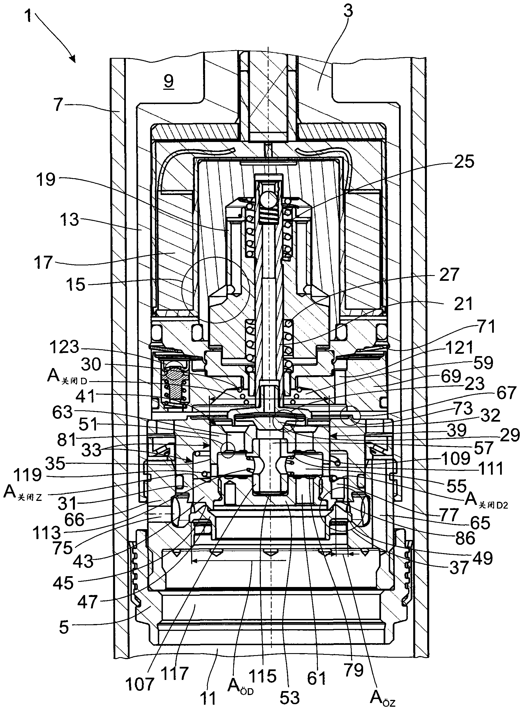
[0022] figure 1 Shown is a damping valve arrangement 1 , which is fastened, for example, to a piston rod 3 of a shock absorber, which is only partially shown. The damping valve arrangement 1 comprises a piston 5 which divides the cylinder 7 into a piston rod-side working chamber 9 and a piston rod-distal working chamber 11 which are filled with a damping medium. In this exemplary embodiment, the damping valve arrangement is fixed on the piston rod 3 , however, the invention is not restricted to this type of arrangement.

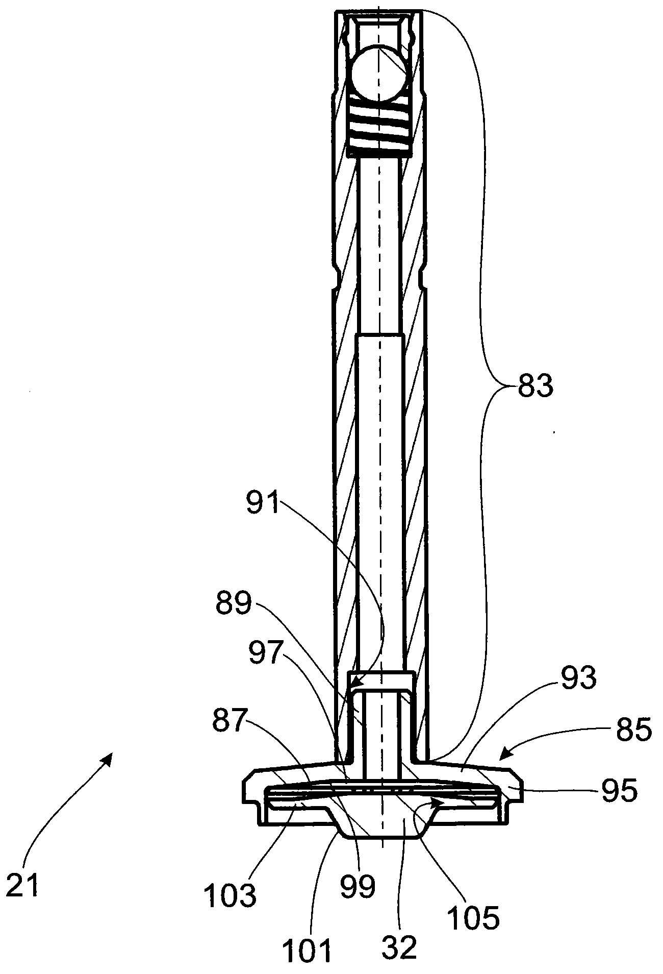
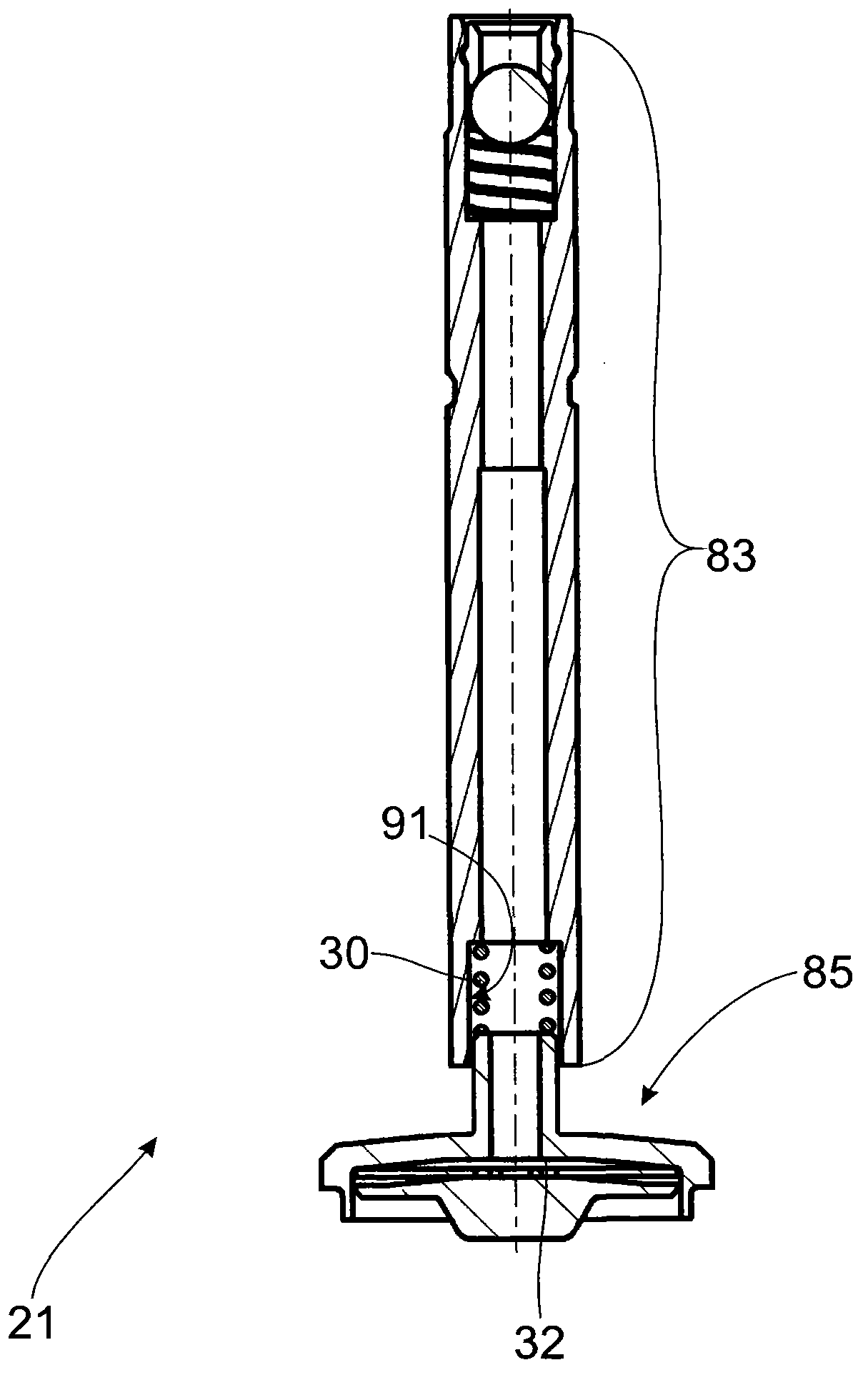
[0023] An actuator 15 of any desired design is arranged in the outer housing 13 , wherein in this exemplary embodiment an electromagnetic coil 17 is used as an actuator, which exerts a force on an axially movable armature 19 , which is controlled by to the multi-part pilot valve body 21 of the pilot valve 23 . The structure of the pilot valve body and figure 2 Get in touch for a detailed description. At least one valve spring (in this variant two counter...


PUM


Abstract

An adjustable damping valve arrangement for a vibration damper comprises an actuator which exerts an actuating force on a multiple-part pilot valve body of a pilot valve. The pilot valve influences a closing force on a main valve via a pilot valve closing body which is movable axially relative to a shaft portion on the actuator side to determine the pressure level in a control cavity of the damping valve arrangement. During lift movement, a main valve body of the main valve compresses a rear cavity connected to the control cavity via the pilot valve. A pilot valve closing spring acts upon the pilot valve closing body in closing direction independently from the actuator control. The rear cavity has a flow-off channel having a damping valve which generates a damping force during the lift movement of the main valve body and when the rear cavity is closed.

Description

technical field [0001] The invention relates to an adjustable damping valve arrangement according to the preamble of claim 1 . Background technique [0002] Document DE 10 2009 016 464 B3 shows an adjustable damping valve arrangement with a pilot valve having a two-part pilot valve body. The armature of the electromagnetic actuator is fastened to the central carrier. The valve seat body actuating the flow cross-section of the control chamber rests against the end face. The pressure acting on the pressure-loaded surface on the main valve body is adjusted by the size of the flow cross section for determining the closing force. [0003] Regardless of the direction of movement of the piston rod, in this particular arrangement the adjustable damping valve arrangement located outside the working chamber is always supplied from one direction only and the damping medium flows out into the compensating chamber. [0004] However, the damping valve device can also be arranged on the...

Claims


Application Information

Patent Timeline
Patent Type & Authority Applications(China)
IPC IPC(8): F16F9/34F16F9/44
CPCF16F9/464F16F9/465F16F9/34F16F9/446
Inventor A·弗尔福特
Owner ZF FRIEDRICHSHAFEN AG
Learn More