Floor heating water division and water collection device

A water collector and floor heating technology, which is applied in the field of building floor heating equipment, can solve the problems of difficult temperature control, easy to affect flow, and inaccuracy, and achieve hydraulic balance, reliable sealing structure, and reliable operation.

Inactive Publication Date: 2014-01-15
TIANJIN HAOWEI ENERGY SAVING ENVIRONMENTAL PROTECTION TECH DEV
View PDF0 Cites 2 Cited by
  • Summary
  • Abstract
  • Description
  • Claims
  • Application Information

AI Technical Summary

Problems solved by technology

[0004] At present, water separators and water collectors cannot directly control the water pressure and water temperature in the pipeline system. It is sometimes not very accurate to control the temperature by manually adjusting the flow rate. Water is directly added to the main pipe without treatment. If the time is long, the impurities in the water will easily affect the flow

Method used


Image

  • Floor heating water division and water collection device

Examples


Embodiment Construction

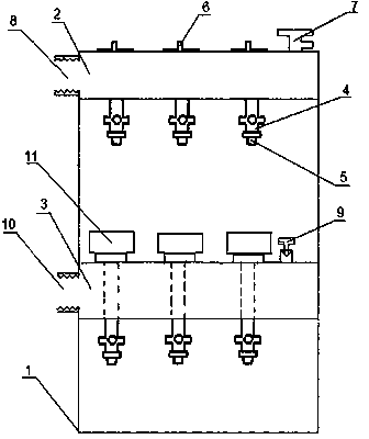
[0012] Such as figure 1 as shown,

[0013] The technical solution of the present invention is: a floor heating sub-collector, including a bracket 1, a water distribution pipe 2 installed on the bracket 1, and a water collection pipe 3. The water pipe 3, the water distribution pipe 2 and the water collection pipe 3 are on the same vertical plane, but the water distribution pipe 2 and the water collection pipe 3 are staggered in the vertical direction, so that the local heating pipelines connected to the bottom of the water distribution pipe 2 pass through, and the water distribution pipe 2 The bottoms of the water pipe 2 and the water collecting pipe 3 are provided with a plurality of branch pipes 4 with ball valves. One end of the branch pipes 4 with ball valves is fixed to the water distribution pipe 2 and the water collecting pipe 3 by welding, and the other end is an externally threaded inner conical surface, which is connected with a looper. One end of the ball head of t...


PUM


Abstract

The invention provides a floor heating water division and water collection device. The floor heating water division and water collection device comprises a support, a water division pipe and a water collection pipe, wherein the water division pipe and the water collection pipe are installed on the support. The water division pipe is located at the upper end of the support; the water collection pipe is installed below the water division pipe; the water collection pipe and the water division pipe are located in the same vertical plane; each branch pipe, located on the water division pipe, with a ball valve and a temperature control valve core are fixedly connected to the water division pipe; each branch pipe, located on the water collection pipe, with a ball valve is provided with an electric heating actuator; the electric heating actuators are connected with a pin-type valve core. The floor heating water division and water collection device has the advantages that because the hot melting technology and the traditional pipe thread sealing technology are combined and used for the connection portion, hidden leakage dangers of heating pipeline clamping sleeve sealing are avoided, and the sealing structure of the water division pipe and the water collection pipe is more reliable; the whole floor heating pipeline system is controlled through control over the temperature of each branch, the hydraulic power of the whole pipeline system is balanced and the whole pipeline system is more reliable to operate.

Description

[0001] technical field [0002] The invention belongs to the technical field of building floor heating equipment, and in particular relates to a floor heating manifold. Background technique [0003] With the improvement of people's living standards, people not only have requirements for the comfort of the living environment, but also have higher and higher requirements in terms of safety, environmental protection and energy saving. The sub-collector is composed of a water-distributing main pipe and a water-collecting main pipe. The water-dividing main pipe is connected to the water supply pipe of the pipe network system. Its main function is to distribute the hot water from the pipe network system to the room for heating through the floor heating pipe buried under the floor. each room. When hot water flows in the floor heating pipe, heat is transferred to the floor, and then radiated to the room through the floor. The other end of the floor heating pipe is connected to the...

Claims


Application Information

Patent Timeline
Patent Type & Authority Applications(China)
IPC IPC(8): F24D3/10
Inventor 武丽红
Owner TIANJIN HAOWEI ENERGY SAVING ENVIRONMENTAL PROTECTION TECH DEV
Why Eureka
Try Eureka