
Method for measuring swing arm ball head stress

A swing arm ball head and ball pin technology, which is applied in the direction of measuring force, measuring devices, instruments, etc., can solve the problems of high price, data accuracy discount, long test cycle, etc., and achieve low cost, high versatility, and measurement The result is precise effect

Inactive Publication Date: 2014-01-15
CHONGQING CHANGAN AUTOMOBILE CO LTD
View PDF5 Cites 7 Cited by
  • Summary
  • Abstract
  • Description
  • Claims
  • Application Information

AI Technical Summary

Problems solved by technology

[0004] This method requires imported wheel six-component force sensors, which are not only expensive, but also need to make corresponding wheel adapters to measure different models, and the test cycle is longer; the measurement results need to be further decomposed to obtain the force of specific parts, which also makes the data accurate. Greatly compromised accuracy

Method used


Image

  • Method for measuring swing arm ball head stress
  • Method for measuring swing arm ball head stress
  • Method for measuring swing arm ball head stress

Examples


specific Embodiment approach

[0016] The specific embodiment of the present invention comprises the following steps:

[0017] A. Preparation: first use coarse sandpaper to remove the surface coating at the position to be patched, and polish it smooth; measure the diameter of the largest circle of the ball head cone, calculate the 1 / 4 arc length, and use a vernier caliper to divide the largest circle of the cone into For 4 1 / 4 arcs, use a scribe to deepen the traces of the dividing points; use fine sandpaper to polish the four patch positions determined after scribing along the axis at a 45-degree angle until the surface is smooth; use tweezers to hold a small amount of cotton and dip it in alcohol , scrub the patch position in one direction, and replace the cotton until there is no stain on the cotton.

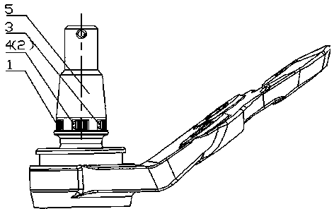
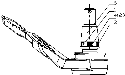
[0018] B. Strain gauge pasting: such as Figure 1-Figure 2 As shown, paste the strain gauges R1, R2, R3, and R4 on the left swing arm ball head 5 and the right swing arm ball head 6 with the same pasting ...


PUM


Abstract

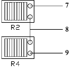
Provided is a method for measuring swing arm ball head stress. First, four strain pieces are bound on the front largest circle, the back largest circle, the left largest circle and the right largest circle of a swing arm ball head at equal distance respectively and are parallel to the axial direction of a ball head pin. The front strain piece and the back strain piece are connected in series to form a limb half bridge, and when the swing arm ball head bears front-back direction stress of a vehicle, X-direction stress of the swing arm ball head can be measured by measuring the output voltage of a bridge circuit. The left strain piece and the right strain piece are connected in series to form a limb half bridge, and Y-direction stress of the swing arm ball head can be measured. Then an actuator is used for carrying out longitudinal and lateral loading on the swing arm ball head respectively and recording loading force, data collecting equipment is used for recording corresponding strain, and a changing relationship curve of strain and force is obtained by fitting. Finally, measuring is carried out. According to the method, a special force sensor is of no need, cost is low, measuring results are accurate, real-vehicle measuring can be carried out on stress of various swing arm ball heads of vehicles of different types, and universality is high.

Description

technical field [0001] The invention belongs to the technical field of automobile testing, and in particular relates to a method for measuring the force of a swing arm ball joint on an automobile suspension during automobile driving. Background technique [0002] The swing arm ball joint is a component that connects the swing arm and the steering knuckle in the car suspension system, and it mainly bears the longitudinal force and lateral force during the driving of the car. When designing the structure of the swing arm ball joint, in order to ensure the strength, it is necessary to know its actual stress, which is also an important input load for the design and analysis of the suspension system. [0003] At present, there is no method to directly measure the force of the swing arm ball joint. To obtain the force of the swing arm ball joint during the driving process of the car, it is necessary to use the wheel six-component force sensor to measure the force at the center of...

Claims


Application Information

Patent Timeline
Patent Type & Authority Applications(China)
IPC IPC(8): G01L1/22
Inventor 王万英罗英唐轶侃郑安普方川
Owner CHONGQING CHANGAN AUTOMOBILE CO LTD
Learn More