Moving object detecting device based on microwave transducer and ultrasonic transducer

A technology of moving objects and detection devices, which is applied in the directions of measuring devices, geophysical measurement, electromagnetic wave re-radiation, etc. It can solve problems such as troublesome installation and construction, errors in detection technology, poor anti-interference ability, etc., and achieve convenient installation and wiring and fast response Fast and requires little space for installation

Inactive Publication Date: 2014-01-15
武汉华大石居科技有限公司
View PDF4 Cites 16 Cited by
  • Summary
  • Abstract
  • Description
  • Claims
  • Application Information

AI Technical Summary

Problems solved by technology

[0006] The purpose of the present invention is to solve the deficiencies in the prior art, and provide a moving object detection device based on microwave and ultrasonic sensors, which has the advantages of small size, fast response speed, and low power consumption, and can cope with different environments And to realize the detection of low-speed moving objects, it better solves the existing problems of pressure sensors, pyroelectric infrared sensors and visual image-based detection technologies such as large errors, troublesome installation and construction, poor anti-interference ability, and expensive prices.

Method used


Image

  • Moving object detecting device based on microwave transducer and ultrasonic transducer
  • Moving object detecting device based on microwave transducer and ultrasonic transducer
  • Moving object detecting device based on microwave transducer and ultrasonic transducer

Examples


Embodiment 1

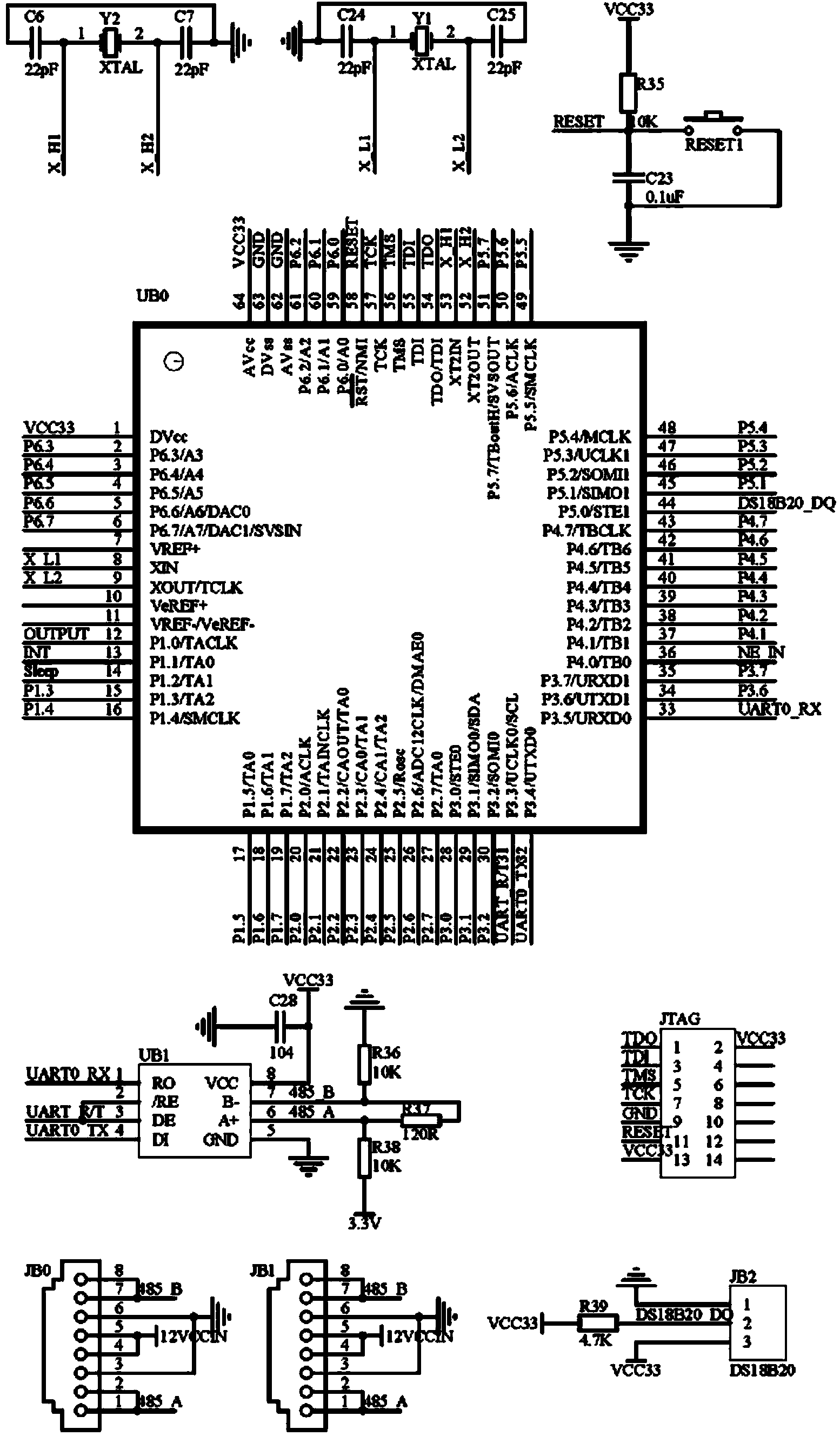
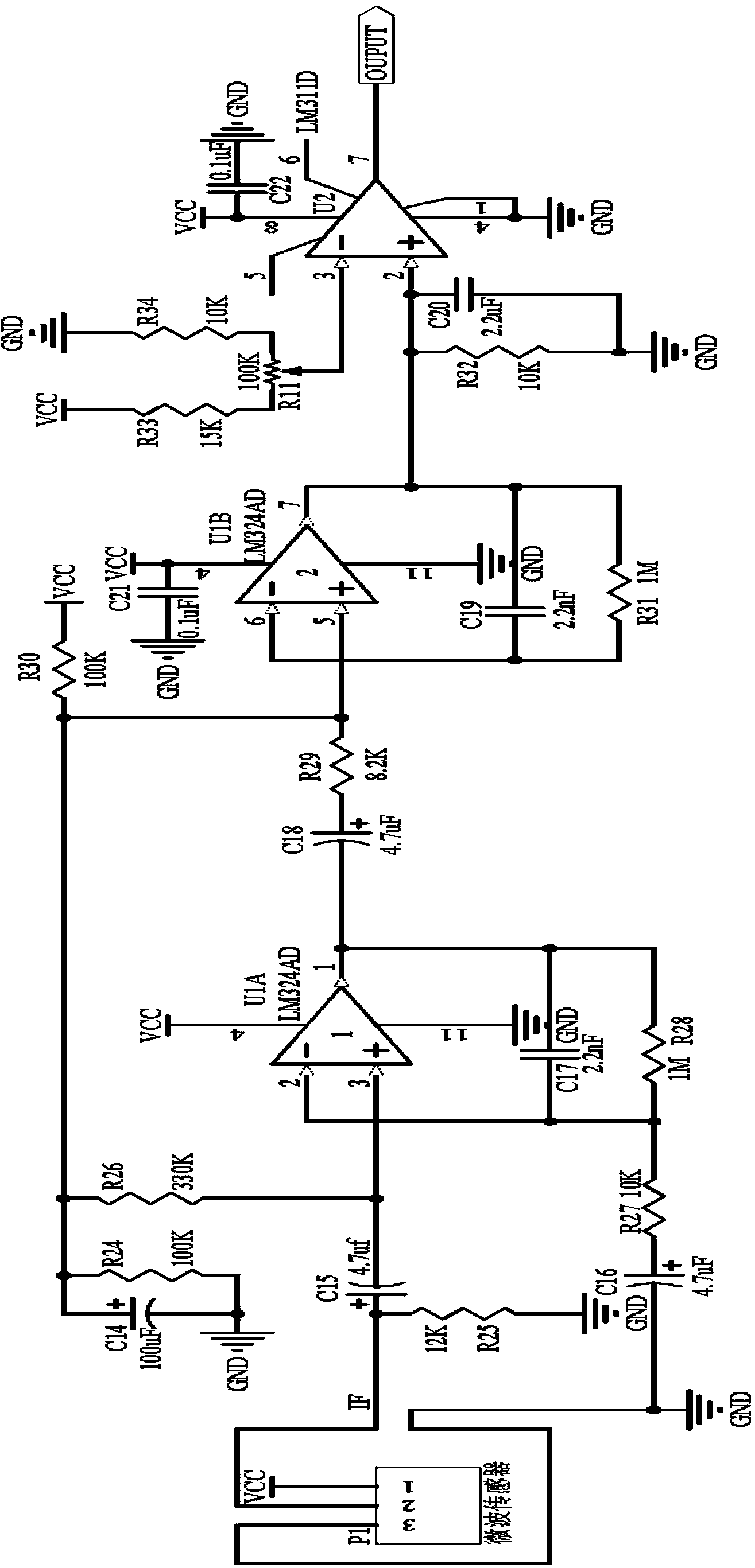
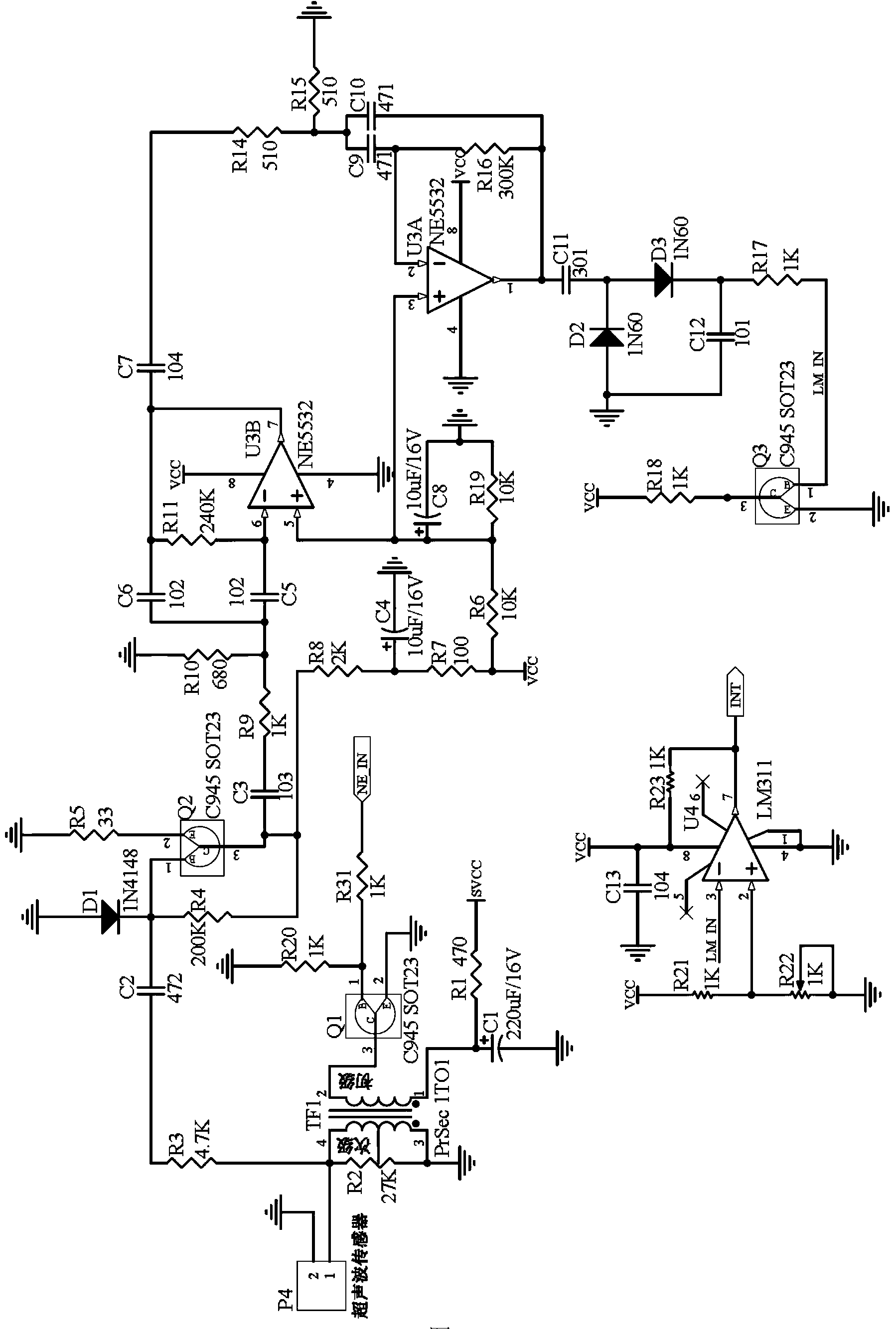
[0032] Embodiment 1: The present invention provides a kind of moving object detection device based on microwave and ultrasonic sensor, its structure is as follows figure 1 shown. It includes microwave and ultrasonic sensors, signal amplification and filtering processing circuits, low-power microcontroller units, field bus interface units, temperature sensors and power supply units. The microwave and ultrasonic sensors include microwave sensors and ultrasonic sensors, microwave sensors and signal The amplification and filtering processing circuit is electrically connected in one direction, the ultrasonic sensor is electrically connected to the signal amplification and filtering processing circuit in two directions, the signal amplification and filtering processing circuit is electrically connected in two directions to the low-power microcontroller unit, and the low-power consumption microcontroller unit is also connected separately It is bidirectionally electrically connected w...

Embodiment 2

[0041] Embodiment 2: Install the moving object detection device based on microwave and ultrasonic sensors provided in Embodiment 1 of the present invention on the ceiling, such as Figure 6 shown. A detection area is formed under the ceiling. When someone enters the detection area, the moving object detection device 1 installed on the ceiling starts to work. The microwave sensor first detects that someone 4 enters the microwave sensor detection area 2, and immediately turns on the ultrasonic sensor. The ultrasonic sensor also detects When someone enters the detection area 3 of the ultrasonic sensor, after entering the detection area, the human body's height, jumping, beckoning, walking and other actions and states are recognized, and the relevant detection data is transmitted to the console to control the related equipment connected with the detection device to the human body. Movement responds.

[0042] The workflow of the moving object detection device based on microwave an...

Embodiment 3

[0053] Embodiment 3: Install multiple moving object detection devices based on microwave and ultrasonic sensors provided in Embodiment 1 of the present invention on the ceiling, and combine them with lamps with DMX to form an interactive light array arrangement. The structure is as follows Figure 8 shown. The lamp 5 with DMX is connected with the moving object detection device 1 of the microwave and ultrasonic sensors respectively through the RS485 bus interface of the field bus 6 . A 6×6 matrix is ​​adopted, the interval between every two moving object detection devices 1 and between every two lamps 5 with DMX is 50 cm, the moving object detection devices 1 are arranged next to the lamps 5 with DMX, and the console 7 through the RS485 bus interface of the field bus 6 to realize two-way electrical connection with the lamp 5 with DMX and the moving object detection device 1 respectively. As long as someone enters the detection array composed of multiple microwave and ultrason...


PUM


Abstract

The invention relates to a moving object detecting device based on a microwave transducer and an ultrasonic transducer. The moving object detecting device comprises a low-power dissipation microcontroller unit, the microwave transducer, the ultrasonic transducer, a signal amplifying and filtering processing circuit, a field bus interface unit, a temperature transducer and a power source unit. The microwave detecting technology and the ultrasonic detecting technology are combined. The detecting distance of the microwave transducer is far, the response speed is high, the anti-jamming capability is high, the measuring precision of the ultrasonic measurement is high, and the angle range is small. When the microwave transducer detects that a moving object passes a detecting area, the ultrasonic transducer is started immediately to confirm that the object enters the detecting area, and the distance and speed information can be obtained. The moving object detecting device is compact in structure and capable of dealing with different environments and detecting the low-speed moving object, the problems that an existing detecting technology based on a pressure transducer, a pyroelectric infrared transducer and visual patterns is large in error, poor in anti-jamming capability and the like are well solved, and the problems that installation and construction are difficult are solved. The moving object detecting device has the advantages of being small in size, high in response speed and low in power consumption.

Description

technical field [0001] The invention relates to a moving object intelligent detection technology, in particular to a moving object detection device based on microwave and ultrasonic sensors. Background technique [0002] At present, to monitor an object, especially the movement of the human body, three methods are mainly used: pressure sensor, pyroelectric infrared sensor and visual image-based. These technologies are relatively mature, but there are some shortcomings, such as the volume of the device used in some methods Too large and inconvenient to install; some methods have too large detection range and poor detection accuracy, and some methods are expensive and cannot detect slow-moving objects. [0003] The method of arranging pressure sensors is used to detect human body movement. For example, in China in December 2011, the pressure sensor is installed under high-strength tempered glass, and the pressure on the top of the matrix block is detected to detect whether the...

Claims


Application Information

Patent Timeline
Patent Type & Authority Applications(China)
IPC IPC(8): G01S11/00G01V11/00
CPCG01S13/04G01S17/58
Inventor 程卓张怀刘经龙李明明
Owner 武汉华大石居科技有限公司
Why Eureka
Try Eureka