Substrate structure and package structure

A packaging structure and substrate technology, applied in electrical components, electrical solid devices, circuits, etc., can solve the problems of abnormal electrical reliability of products, narrow spacing, solder 16 bridging, etc. The effect of alignment accuracy

Inactive Publication Date: 2014-01-15
SILICONWARE PRECISION IND CO LTD
View PDF4 Cites 5 Cited by
  • Summary
  • Abstract
  • Description
  • Claims
  • Application Information

AI Technical Summary

Problems solved by technology

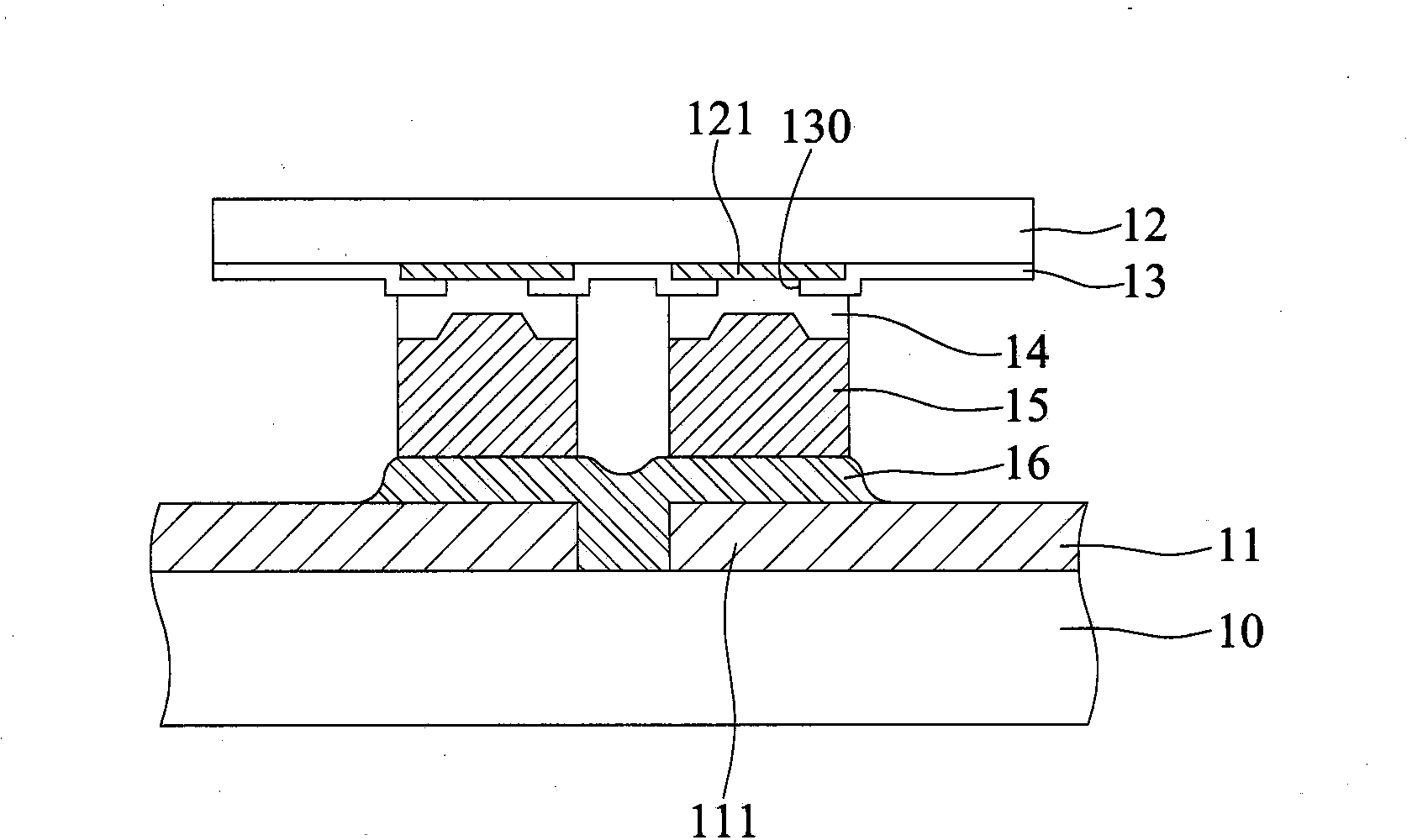
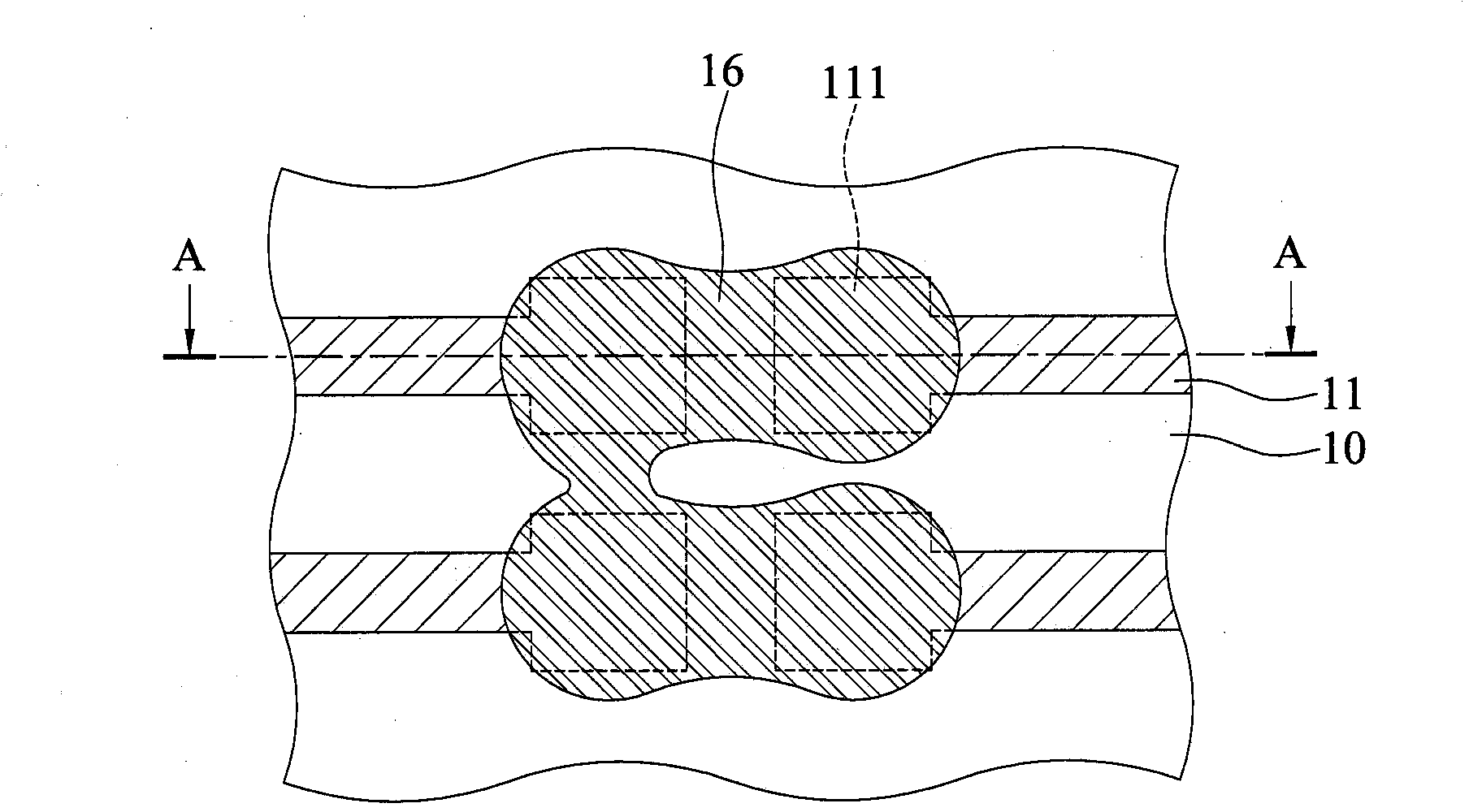
[0006] However, since the size of the electrical contacts 111 is larger than that of the circuit 11, under the requirement that the circuits 11 on the circuit board or package substrate must be thin line width / fine line spacing, the electrical contacts 111 The spacing between 111 will be quite narrow, and when the semiconductor chip 12 is connected with the solder 16, it will be easy to press down when the solder 16 on the metal post 15 is placed on the electrical contact 111 due to the misalignment of the semiconductor chip 12 or the heating. And solder 16 bridging (solder bridge) problem occurs, and then the reliability problem of electrical abnormality occurs in the product

Method used


Image

  • Substrate structure and package structure
  • Substrate structure and package structure
  • Substrate structure and package structure

Examples


Embodiment Construction

[0030] The implementation of the present invention will be described below through specific examples, and those skilled in the art can easily understand other advantages and effects of the present invention from the content disclosed in this specification.

[0031] It should be noted that the structures, proportions, sizes, etc. shown in the drawings attached to this specification are only used to match the content disclosed in the specification for the understanding and reading of those skilled in the art, and are not intended to limit the implementation of the present invention. Limiting conditions, so there is no technical substantive meaning, any modification of structure, change of proportional relationship or adjustment of size, without affecting the effect and purpose of the present invention, should still fall within the scope of the present invention. The disclosed technical content must be within the scope covered. At the same time, terms such as "end", "upper" and "...


PUM


Abstract

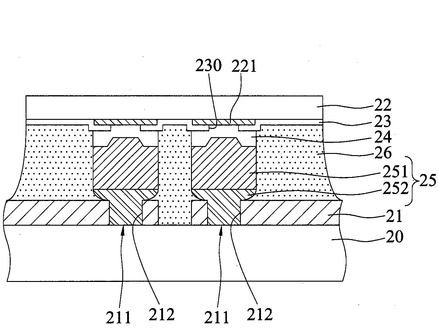
A substrate structure and a package structure are provided. The substrate structure includes a substrate body and a plurality of traces formed on a surface of the substrate body. At least one of the traces has an electrical contact formed in a groove thereof for electrically connecting an external element, thereby meeting the demands of fine line / fine pitch and miniaturization and improving the product reliability.

Description

technical field [0001] The invention relates to a substrate structure and a package structure, in particular to a substrate structure and a package structure of a flip-chip package. Background technique [0002] As the design of electronic products is becoming increasingly thinner and smaller, the circuit board or packaging substrate must also develop in the direction of fine line / fine pitch. [0003] see Figure 1A and Figure 1B , are schematic diagrams of the existing substrate structure and package structure respectively, where, Figure 1A for the top view Figure 1B A cross-sectional view of section line AA, and Figure 1B Some components are omitted. [0004] As shown in the figure, the existing flip-chip process first provides a substrate body 10 that can be a packaging substrate or a circuit board, and a plurality of circuits 11 are formed on a surface of the substrate body 10, and the ends of the circuits 11 have a relatively large area. Large electrical contact...

Claims


Application Information

Patent Timeline
Patent Type & Authority Applications(China)
IPC IPC(8): H01L23/495
CPCH01L21/563H01L23/49838H01L24/13H01L24/16H01L2224/0401H01L2224/05022H01L2224/05572H01L2224/13082H01L2224/131H01L2224/16237H01L2224/73204H01L2224/81191H01L2224/81385H01L2224/82385H01L2924/00014H01L2924/3841H01L2924/014H01L2224/05552
Inventor 林长甫陈锦德姚进财
Owner SILICONWARE PRECISION IND CO LTD
Why Eureka
Try Eureka