A high-power crimping type igbt device

A crimping, high-power technology, applied in the direction of electric solid devices, semiconductor devices, semiconductor/solid state device components, etc., can solve the problems that affect the overall performance of the device, cannot be used universally, and cannot optimize the current path, so as to improve the uniformity of the current. The effect of distribution, suppression of high frequency oscillation, reduction of types and material consumption

Active Publication Date: 2016-04-20
STATE GRID CORP OF CHINA +2
View PDF7 Cites 0 Cited by
  • Summary
  • Abstract
  • Description
  • Claims
  • Application Information

AI Technical Summary

Problems solved by technology

The existing crimping IGBT device sub-module components cannot be used in common, and the layout of the IGBT and FWD chips cannot optimize the current path, thus affecting the overall performance of the device

Method used


Image

  • A high-power crimping type igbt device
  • A high-power crimping type igbt device
  • A high-power crimping type igbt device

Examples


Embodiment Construction

[0037] The specific implementation manners of the present invention will be further described in detail below in conjunction with the accompanying drawings.

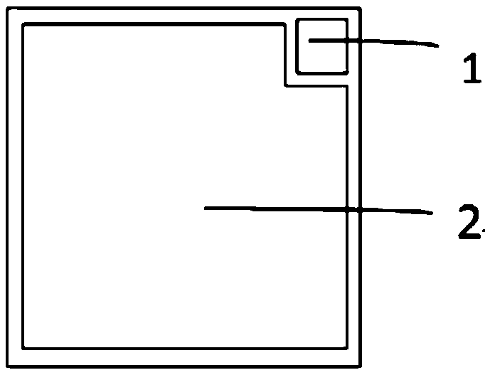
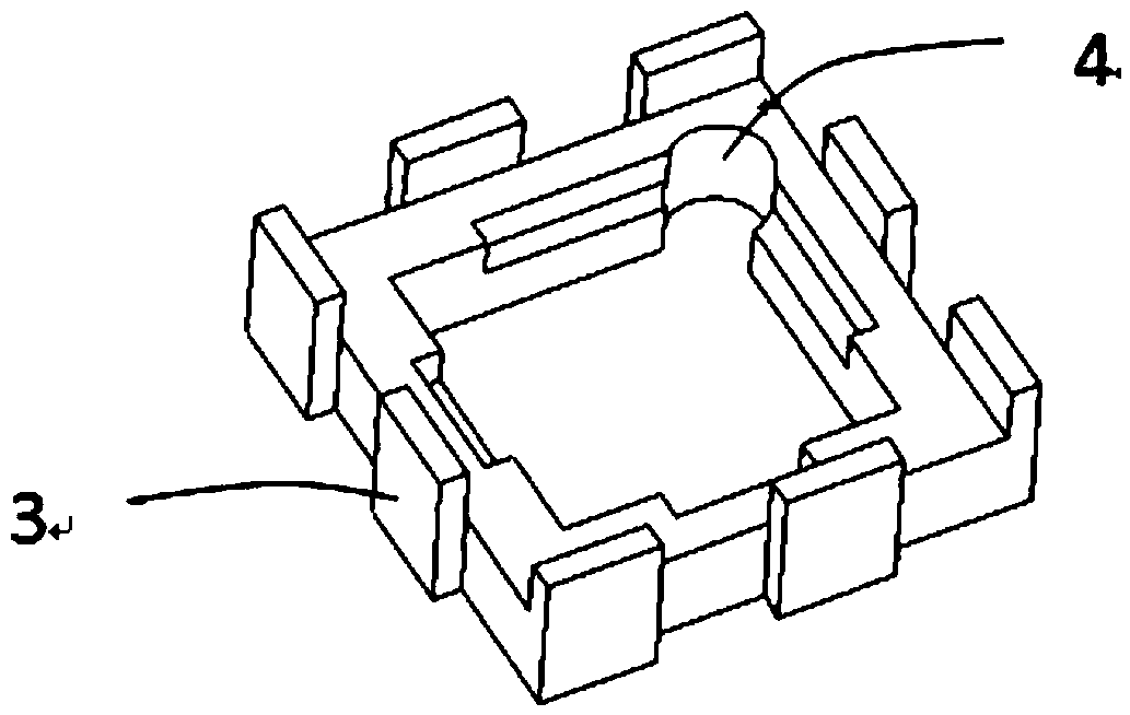
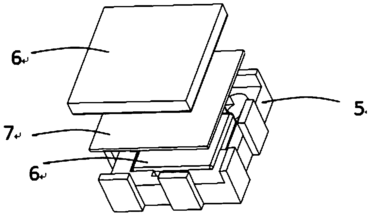
[0038] The invention provides a high-power crimping type IGBT device. The appearance of the crimping IGBT device is composed of two power electrodes and a ceramic shell on the side. The two power electrodes are respectively arranged at both ends of the shell. Inside the two power electrodes are a plurality of sub-modules containing power chips, and each sub-module contains a power chip. Depending on the current level of the entire device, there are several to dozens of power chips connected in parallel inside the crimping IGBT device, that is, several to dozens of sub-modules. The power chip inside the crimping IGBT device includes an IGBT chip and a freewheeling diode FWD chip connected in antiparallel to it. Typically, IGBT chips and FWD chips are rectangular thin silicon wafers with a thickness of several hundred mic...


PUM


Abstract

The invention relates to a large power crimping type IGBT device. The IGBT device is a cylindrical or rectangular body. The IGBT device comprises a tube casing and two power electrodes which are arranged on upper and lower ends of the tube casing. The upper power electrode is in a flat plate structure. A boss array is distributed on one side of the lower power electrode. In the device, a sub module is arranged on each boss. The sub modules are divided into two kinds of IGBT sub modules and FWD sub modules. IGBT and FWD sub modules comprise power chips, a number of metal gaskets and insulating frames. The power chips comprise two groups of IGBT chips and FWD chips. The IGBT chips and the FWD chips in the sub modules are rectangular silicon wafers with the thickness of 100 to 1000 microns. No solder joint is in the crimping IGBT device. In practical application, depending on pressure of dozens of newtons applied outside the device, the chips and upper and lower power electrodes are well connected. The reliability of the device is improved, and the process complexity is reduced.

Description

technical field [0001] The invention relates to a power device, in particular to a high-power crimping type IGBT device. Background technique [0002] At present, the most rapidly developing power electronic device, insulated gate bipolar transistor (IGBT), is widely used in new energy, power transmission and transformation, rail transit, metallurgy, chemical industry and other fields. Compared with the traditional soldered modular IGBT devices, the press-fit IGBT has the advantages of no solder joints, bilateral cooling, and high reliability. Failure causes the operation of the entire device to be interrupted, so it is very suitable for power system applications with high withstand voltage requirements. The sub-module components of existing crimped IGBT devices cannot be used in common, and the layout of IGBT and FWD chips cannot optimize the current path, thereby affecting the overall performance of the device. Contents of the invention [0003] In view of the deficien...

Claims


Application Information

Patent Timeline
Patent Type & Authority Patents(China)
IPC IPC(8): H01L25/07H01L23/13H01L23/492H01L25/00H01L29/423H01L29/739
Inventor 张朋包海龙张宇刘隽车家杰韩荣刚金锐于坤山
Owner STATE GRID CORP OF CHINA
Why Eureka
Try Eureka