External-cavity laser device with tunable wave length

A technology of lasers and wavelengths, applied in the field of lasers, can solve problems such as insufficient bandwidth, storage problems, and DFB lasers that cannot meet the wavelength range, and achieve high reliability, low cost, and reduced networking costs and network complexity. Effect

Inactive Publication Date: 2014-01-15
INNOLIGHT TECHNOLOGY (SUZHOU) LTD
View PDF5 Cites 27 Cited by
  • Summary
  • Abstract
  • Description
  • Claims
  • Application Information

AI Technical Summary

Problems solved by technology

In the WDM-PON system, when the optical network unit (ONU, Optical Network Unit) performs data uplink transmission, lasers with different wavelengths must be used, and in the WDM-PON system, due to the ease of operation and high reliability, distributed Feedback (DFB, Distributed Feedback) lasers are widely used, but the bandwidth of DFB lasers is not wide enough to achieve wavelength tuning in a wide range. Therefore, DFB lasers cannot meet the wavelength range required by multiple ONUs. The use of DFB laser technology in WDM-PON systems will not only lead to expensive wavelength management costs, but also cause serious storage problems
To solve this problem, so far, Arrayed Waveguide Gratin (AWG, Arrayed Waveguide Gratin) technology is mainly used. By controlling the current and temperature of the laser, and tuning the wavelength of the grating Bragg (Bragg), the uncoated Fabry-Perot The external cavity laser composed of FP (FP, Fabry-Pero) laser and grating can output single-mode light at different wavelengths, but the side-mode suppression ratio (SMSR, Side-Mode Suppression Ratio) and reliability of this technology need to be further improved

Method used


Image

  • External-cavity laser device with tunable wave length
  • External-cavity laser device with tunable wave length
  • External-cavity laser device with tunable wave length

Examples


Embodiment Construction

[0027] The present invention will be described in further detail below in conjunction with the accompanying drawings.

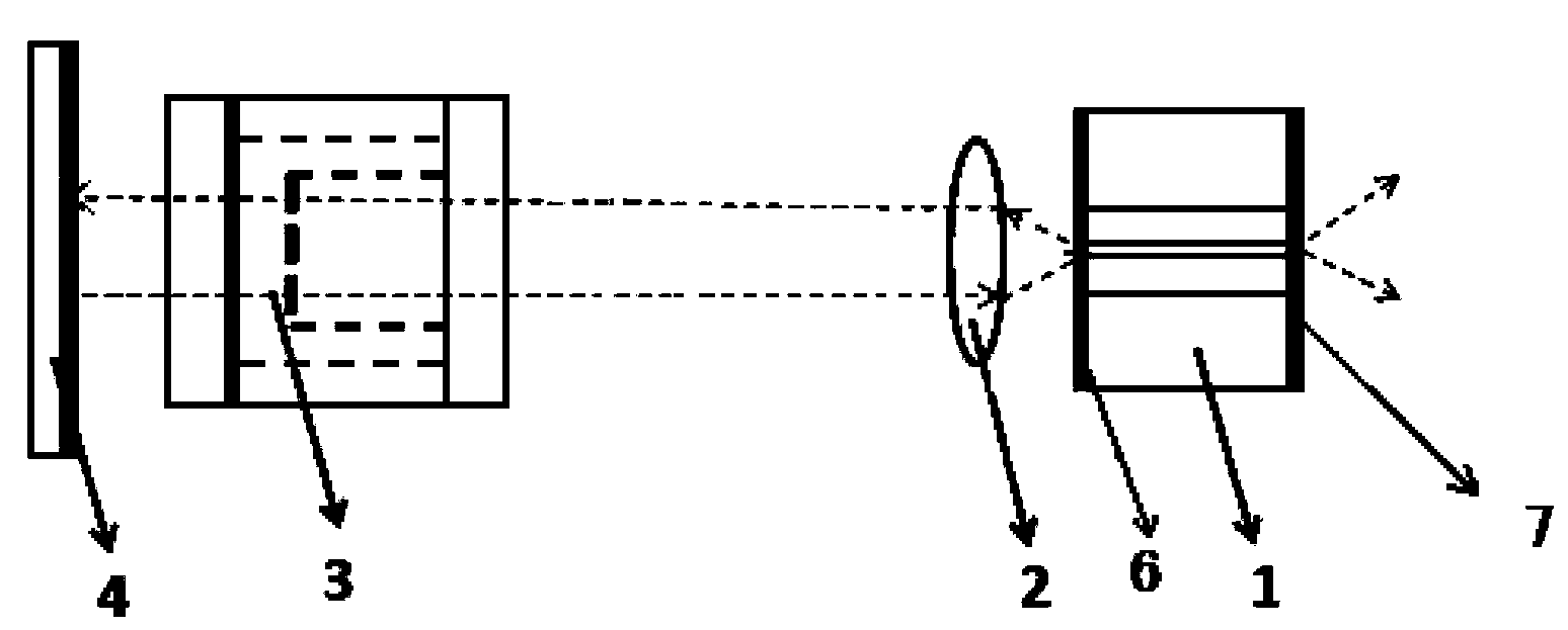
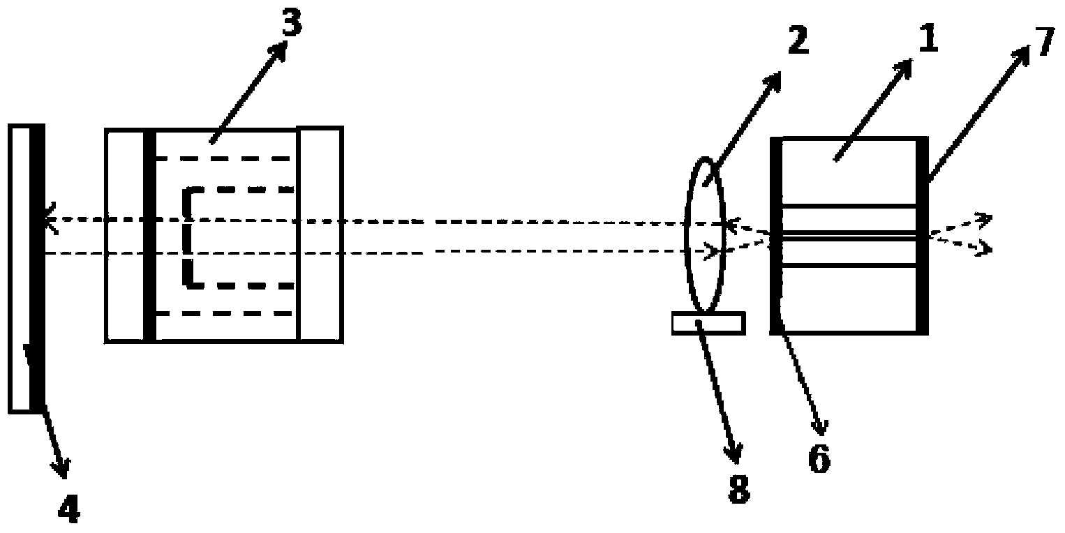
[0028] figure 1 A schematic diagram showing the structure of a wavelength tunable external cavity laser according to an embodiment of the present invention, which includes a laser gain chip 1, and a lens unit 2 that is located on one side of the laser gain chip 1 and constitutes an external cavity feedback area, and an optical etalon 3 and reflector 4, wherein the end surface of the laser gain chip 1 facing the external cavity feedback area is coated with an anti-reflection film 6, and the other end surface is coated with a partial transmission and partial reflection film 7; the laser gain chip 1 is coated with an anti-reflection film 6 The lens unit 2, the optical etalon 3 and the reflector 4 are arranged in sequence from one side; wherein, the lens unit 2, the optical etalon 3 and the reflector 4 are arranged so that the external cavity feedback area and th...


PUM


Abstract

The invention aims to provide an external-cavity laser device with a tunable wave length. Particularly, the external-cavity laser comprises a laser gain chip, one or more lens units, an optical etalon and a reflector, wherein the one or more lens units, the optical etalon and the reflector are located on one side of the laser gain chip and constitute an external-cavity feedback region; the end face, facing the external-cavity feedback region, of the laser gain chip is plated with an antireflection film, and the other end face of the laser gain chip is plated with a partial-transmission partial-reflection film; from the side, plated with the antireflection film, of the laser gain chip, the one or more lens units, the optical etalon and the reflector are sequentially arranged; the one or more lens units, the optical etalon and the reflector are arranged so as to make the external-cavity feedback region and the laser gain chip constitute a laser resonant cavity. Compared with the prior art, the external-cavity laser device has the advantages of having the large-range output wave length of a multi-longitudinal-mode laser, high reliability, low cost and the like.

Description

technical field [0001] The invention relates to the technical field of lasers, in particular to a technology of a wavelength-tunable external cavity laser. Background technique [0002] Wavelength Division Multiplexing PON (WDM-PON, Wavelength Division Multiplexing PON) is the most visionary and scalable solution to provide end users with high bandwidth, which combines the advantages of WDM technology and PON topology. WDM technology refers to the technology of combining several channels of modulated optical signals through a multiplexer (or wavelength division multiplexer) according to a certain wavelength interval and transmitting them through an optical fiber. In the WDM-PON system, when the Optical Network Unit (ONU, Optical Network Unit) performs data uplink transmission, lasers with different wavelengths must be used, and in the WDM-PON system, due to the ease of operation and high reliability, distributed Feedback (DFB, Distributed Feedback) lasers are widely used, b...

Claims


Application Information

Patent Timeline
Patent Type & Authority Applications(China)
IPC IPC(8): H01S5/14H01S5/06
CPCH01S5/141G02B5/284H01S3/1062H01S5/0612H01S5/06804
Inventor 李伟龙李虹孙雨舟王祥忠刘圣
Owner INNOLIGHT TECHNOLOGY (SUZHOU) LTD
Why Eureka
Try Eureka