Permanent-magnet type rotating electrical machine

A technology of rotating electrical machines and permanent magnets, applied in the direction of magnetic circuit rotating parts, magnetic circuits, electrical components, etc., can solve the problems of difficult processing of magnetic steel plates, difficulty in improving the accuracy of the outer diameter of the rotor core, etc., to maintain accuracy and reduce torque ripple effect

Active Publication Date: 2014-01-15
MITSUBISHI ELECTRIC CORP
View PDF8 Cites 6 Cited by
  • Summary
  • Abstract
  • Description
  • Claims
  • Application Information

AI Technical Summary

Problems solved by technology

As a result, there is a problem that it is difficult to process the laminated magnetic steel sheets, and it is difficult to improve the accuracy of the outer diameter of the rotor core.

Method used


Image

  • Permanent-magnet type rotating electrical machine
  • Permanent-magnet type rotating electrical machine
  • Permanent-magnet type rotating electrical machine

Examples


Embodiment approach 1

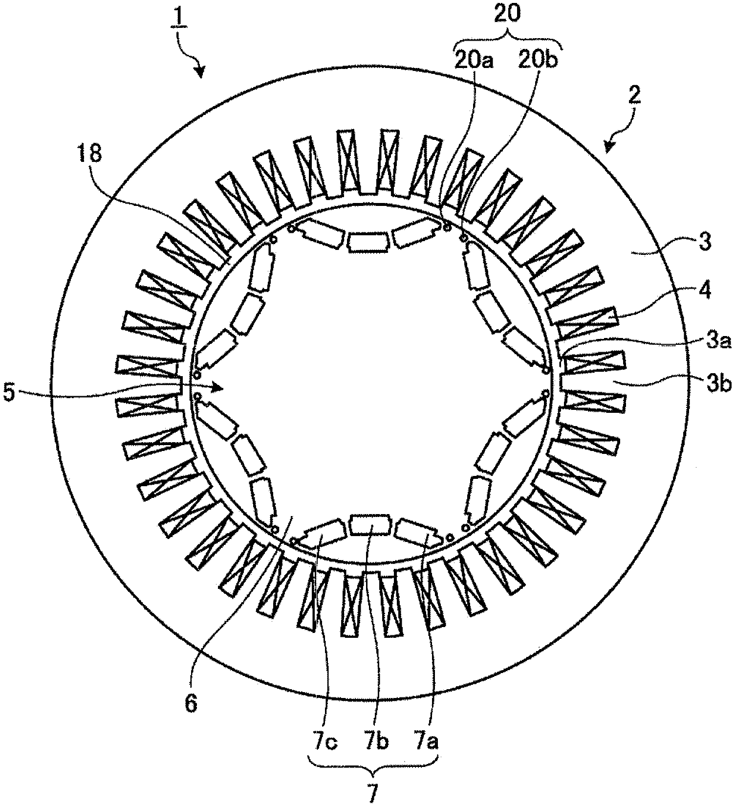
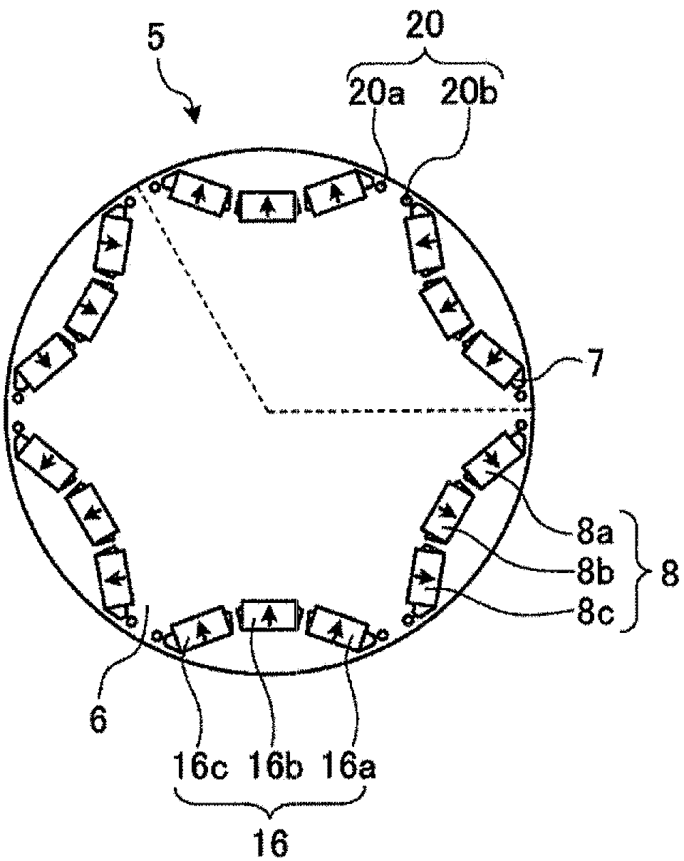
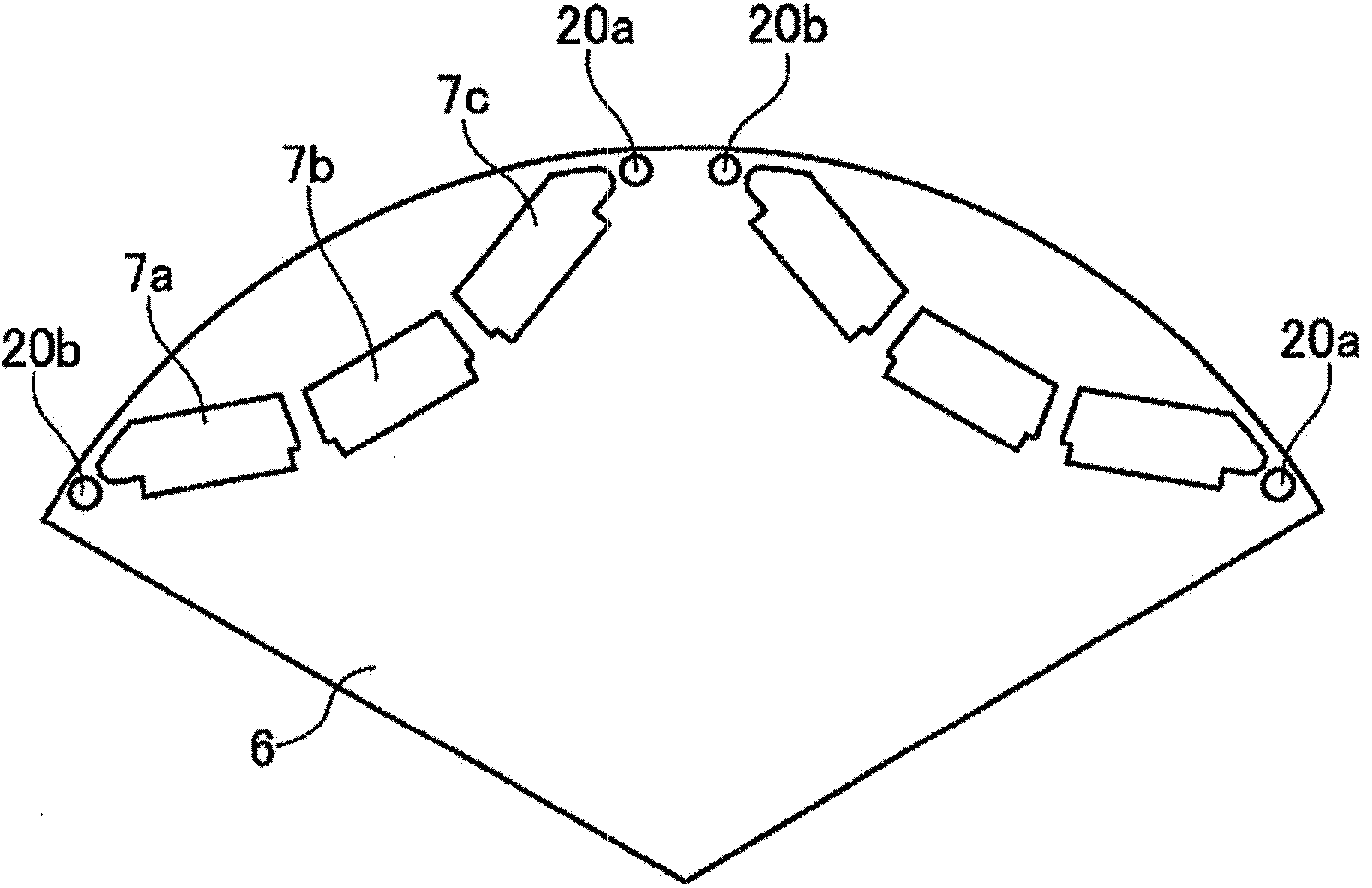
[0028] figure 1 Is a cross-sectional view of a permanent magnet type electric motor as an example of the permanent magnet type rotating electric machine according to the first embodiment, figure 2 Is a schematic cross-sectional view of the rotor showing the magnetic pole structure of the permanent magnets embedded in the rotor, image 3 Yes figure 2 A partial enlarged view of the part shown by the dotted line in the case where no permanent magnet is inserted, Figure 4 Is in the case of inserting permanent magnets and image 3 The corresponding partial enlarged view.

[0029] The permanent magnet motor 1 according to the first embodiment has a stator 2 and a rotor 5. The stator 2 has a stator core 3 formed in a cylindrical shape. On the inner peripheral side of the stator core 3, for example, 36 teeth 3b are formed at equal angular intervals at intervals to form 36 slits 3a. In addition, the stator coil 4 is wound and housed in the slit 3a so as to have a fixed number of teeth 3...

Embodiment approach 2

[0047] In the first embodiment, a pair of magnetic flux control holes 20a, 20b capable of reducing torque ripple are provided in the inter-pole part of the rotor, but these magnetic flux control holes 20a, 20b may be such as Figure 8 The riveting structure as shown. Figure 8 It is an axial cross-sectional view of a magnetic flux control hole formed by a riveting structure.

[0048] In addition, Picture 9 It is a graph (simulation result) showing the relationship between the center distance of the magnetic flux control hole 20 formed by the riveting structure and the amplitude of the torque ripple. In addition, the relationship between the horizontal axis and the vertical axis and the diameter of the magnetic flux control hole 20 as a parameter are the same as those in the first embodiment.

[0049] Such as Picture 9 As shown, regardless of the size (diameter) of the magnetic flux control holes 20, the value (m / τ) obtained by normalizing the center distance m between the magnetic...

Embodiment approach 3

[0053] Picture 10 A schematic cross-sectional view showing a partial structure of the rotor core of the permanent magnet type rotating electrical machine according to the third embodiment. In the first and second embodiments, three permanent magnets are arranged in a substantially U-shape for each pole, but in this embodiment, as Picture 10 As shown, two permanent magnets are arranged in a V shape for each pole, and the same magnetic flux control holes 20a and 20b as in the first embodiment are provided in the inter-pole part.

[0054] In addition, Picture 11 It is a graph (simulation result) showing the relationship between the center distance of the magnetic flux control holes 20 and the amplitude of the torque ripple in the rotor structure according to the third embodiment. In addition, the relationship between the horizontal axis and the vertical axis and the diameter of the magnetic flux control hole 20 as a parameter are also the same as those in the first embodiment.

[0...


PUM


Abstract

The purpose of the invention provides a permanent-magnet type rotating electrical machine. Magnet inserting holes (7a-7c), into which a plurality of permanent magnets are to be embedded for each pole, are formed on a rotor iron-core (6) in protrusion towards the center of the rotor, and pairs of magnetic-flux controlling holes (20a, 20b) that are symmetrical with respect to the centerline between magnetic poles are formed at inter-pole sections (22) of the rotor iron-core (6), for each of the magnetic poles. When the diameter of the magnetic-flux control holes (20a, 20b) is assumed to be d, the distance between the centers is assumed to be m, the width of the inter-pole sections (22) is assumed to be b, and the pitch between the magnetic poles is assumed to be tau, the magnetic-flux control holes (20a, 20b) are formed so that the value of m/tau, which is a value resulting from standardizing the distance between the centers (m) with the pole pitch (tau), will satisfy a relationship of 0.08 (m/tau((b-2d)/tau.

Description

Technical field [0001] The present invention relates to a rotating electric machine such as a vehicle motor, and particularly relates to a structure of a rotor of a rotating electric machine in which permanent magnets are arranged inside the rotor. Background technique [0002] There is a permanent magnet type motor that uses permanent magnets as the magnetic field generation unit of the rotor, and there is also known a permanent magnet type motor that uses the permanent magnet type motor in a high-speed range by embedding permanent magnets inside the rotor to improve centrifugal force resistance A flexible magnet embedded motor (Interior Permanent Magnet Motor: hereinafter referred to as "IPM motor") (for example, Patent Document 1 below). [0003] In the IPM motor described in Patent Document 1, it is proposed to provide slots (slits) between the poles (q-axis) of the rotor to reduce torque ripple. [0004] Prior art literature [0005] Patent literature [0006] Patent Document...

Claims


Application Information

Patent Timeline
Patent Type & Authority Applications(China)
IPC IPC(8): H02K1/27
CPCH02K1/276H02K1/2766H02K2213/03H02K29/03H02K2201/09H02K1/2706
Inventor 枦山盛幸金子健太井上正哉
Owner MITSUBISHI ELECTRIC CORP
Why Eureka
Try Eureka