Switched reluctance motor including u-shaped rotor pole structure

A technology of switched reluctance motors and rotor poles, which is applied in the direction of magnetic circuit shape/style/structure, magnetic circuits, electromechanical devices, etc., and can solve the problem of low power density of switched reluctance motors, unstable operation of switched reluctance motors, and control problems. System complexity and other problems, to achieve the effect of reducing radial vibration, reducing torque ripple, and simplifying the control system

Inactive Publication Date: 2019-08-16
石镇德
View PDF4 Cites 0 Cited by
  • Summary
  • Abstract
  • Description
  • Claims
  • Application Information

AI Technical Summary

Problems solved by technology

However, the traditional switched reluctance motor still has the following disadvantages: 1. The radial vibration generated by the traditional switched reluctance motor during operation is the main cause of the noise of the switched reluctance motor; 2. The traditional switched reluctance motor is running The torque ripple generated in the motor is the main reason for the unstable operation and low efficiency of the switched reluctance motor; 3. The power density of the traditional switched reluctance motor is not high; 4. The traditional four-phase or five-phase or more phase The control system of the switched reluctance motor is complex

Method used


Image

  • Switched reluctance motor including u-shaped rotor pole structure
  • Switched reluctance motor including u-shaped rotor pole structure
  • Switched reluctance motor including u-shaped rotor pole structure

Examples


Embodiment Construction

[0028] In order to enable those skilled in the art to better understand the present invention, specific embodiments of the present invention will be described in detail below in conjunction with the accompanying drawings.

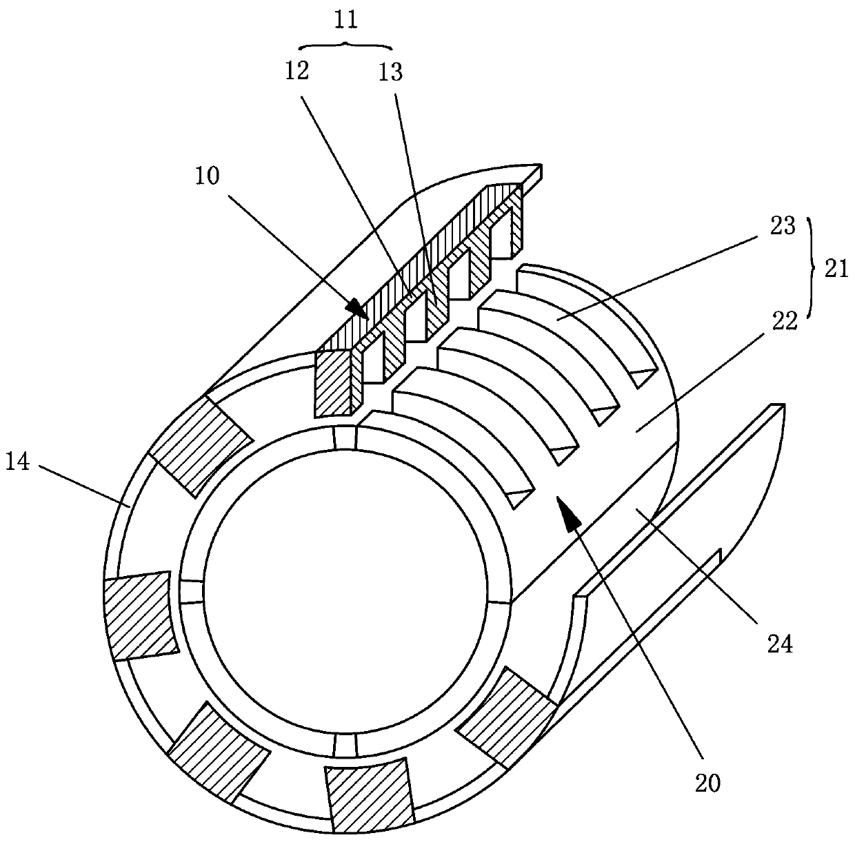
[0029] figure 1 is a schematic structural view of the unidirectional rotary switched reluctance motor according to the first embodiment of the present invention,

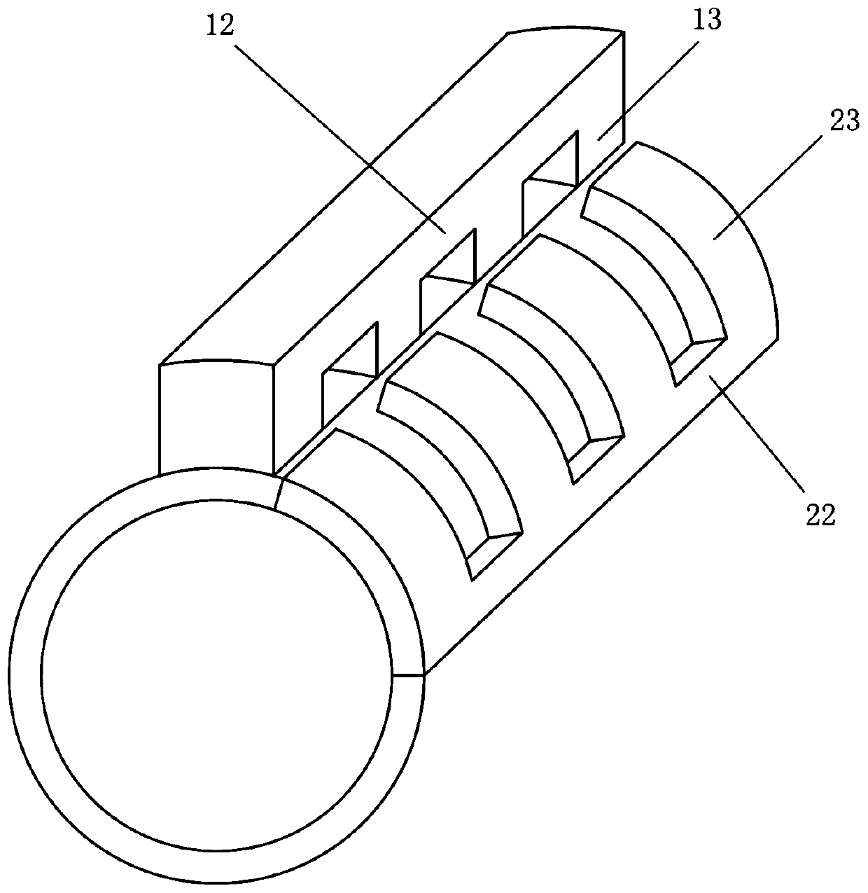
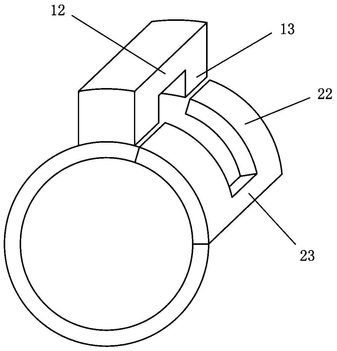
[0030] figure 2 is a partial structural schematic diagram of the unidirectional rotary switched reluctance motor according to the first embodiment of the present invention.

[0031] refer to figure 1 and figure 2 , shows the structure of the unidirectional rotary switched reluctance motor according to the first embodiment of the present invention. In this embodiment, the switched reluctance motor may have an inner rotor outer stator structure or an inner stator outer rotor structure. For ease of description, a switched reluctance motor with an inner rotor and outer stator structure is take...


PUM


Abstract

The invention provides a switched reluctance motor including a U-shaped rotor magnetic pole structure. The switched reluctance motor comprises a stator and a rotor, wherein the stator and the rotor are coaxially arranged. The stator comprises a number of stator magnetic poles uniformly distributed in the circumferential direction. Each stator magnetic pole comprises a stator magnetic pole root anda number of stator magnetic pole teeth extending radially from the stator magnetic pole root toward the rotor. Each stator magnetic pole is wound with a coil. The rotor comprises a number of rotor magnetic poles uniformly distributed in the circumferential direction. Each rotor magnetic pole comprises a rotor magnetic pole root and a number of rotor magnetic pole teeth extending in the circumferential direction from the same side of the rotor magnetic pole root, wherein the rotor magnetic pole teeth and the rotor magnetic pole root share the same curvature. A number of stator magnetic pole teeth and a number of rotor magnetic pole teeth are axially aligned with each other. According to the switched reluctance motor provided by the invention, radial vibration and torque ripple of the motor can be significantly reduced; noise generated by radial vibration can be reduced; and the motor efficiency is improved.

Description

technical field [0001] The invention relates to the field of switched reluctance motors, in particular, the invention relates to a switched reluctance motor including a U-shaped rotor magnetic pole structure which realizes unidirectional rotation. Background technique [0002] Switched reluctance motors have been widely used. However, the traditional switched reluctance motor still has the following disadvantages: 1. The radial vibration generated by the traditional switched reluctance motor during operation is the main cause of the noise of the switched reluctance motor; 2. The traditional switched reluctance motor is running The torque ripple generated in the motor is the main reason for the unstable operation and low efficiency of the switched reluctance motor; 3. The power density of the traditional switched reluctance motor is not high; 4. The traditional four-phase or five-phase or more phase The control system of the switched reluctance motor is complex. Contents o...

Claims


Application Information

Patent Timeline
Patent Type & Authority Patents(China)
IPC IPC(8): H02K1/14H02K1/24H02K29/03
CPCH02K1/146H02K1/246H02K29/03H02K2213/03
Inventor 石镇德
Owner 石镇德
Why Eureka
Try Eureka