A rotor punching structure of a permanent magnet servo motor

A permanent magnet servo motor and rotor punching technology, applied in the direction of magnetic circuit shape/style/structure, magnetic circuit rotating parts, etc., can solve the problem of sinusoidal back electromotive force of no-load phase and unfavorable sine wave drive Problems such as effective control by the controller and no optimization of the air gap flux density can achieve the effect of improving dynamic response performance, improving dynamic response characteristics, and weakening harmonics

Active Publication Date: 2017-11-07
SHANGHAI MOTOR SYST ENERGY SAVING ENG TECH RES CENT +2
View PDF7 Cites 0 Cited by
  • Summary
  • Abstract
  • Description
  • Claims
  • Application Information

AI Technical Summary

Problems solved by technology

The Chinese patent application number 201210419454.3 provides a built-in permanent magnet motor rotor stamping and a built-in permanent magnet motor rotor. The rotor magnetic circuit structure of this solution can effectively avoid magnetic flux leakage at the magnetic isolation bridge, thus making the same The air-gap magnetic field intensity generated by the amount of permanent magnets is greater, which reduces the manufacturing cost, but its magnetic circuit structure still cannot solve the problem of sinusoidal back electromotive force of the no-load phase, especially the quadrature-axis armature reaction magnetic field to the direct-axis magnetic field. The influence of the road is not considered, which will reduce the operating performance of the motor at high speed
The Chinese patent application number 201220079850.1 provides a permanent magnet assisted synchronous reluctance motor. The rotor magnetic circuit structure of this scheme is provided with multi-layer permanent magnet slots and multi-layer magnets, which can make full use of the reluctance torque, but for the air gap The magnetic density is not optimized, and the structure of the rotor punch is round, so that the back electromotive force waveform will not be a standard sine wave, which is not conducive to the effective control of the sine wave drive controller

Method used


Image

  • A rotor punching structure of a permanent magnet servo motor

Examples


Embodiment Construction

[0022] In order to make the present invention more comprehensible, a preferred embodiment is described in detail below with accompanying drawings.

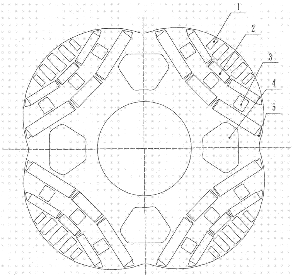
[0023] figure 1 It is a schematic diagram of a rotor punching structure for a permanent magnet servo motor provided by the present invention. The rotor punching structure of a permanent magnet servo motor includes a rotor punching body, and a different number of permanent magnet slots 5 are arranged on the rotor punching body , permanent magnet 2, magnetic isolation hole 1, magnetic isolation slot 3 and axial cooling channel 4, etc.

[0024] The circumferential surface of the rotor punching body is provided with a permanent magnet slot 5, and the permanent magnet 2 is fixedly placed in the permanent magnet slot 5, and fixed in the axial direction with a pressure plate. Permanent magnet groove 5 can be built-in " one " font, also can be built-in " V " type, " U " type or " W " type ( figure 1 Shown as "one" font), the specific me...


PUM


Abstract

The invention provides a rotor punching structure of a permanent magnet servo motor, comprising a rotor punching body, a permanent magnet groove is arranged on the circumferential surface of the rotor punching body, and a permanent magnet is embedded in the permanent magnet groove; the rotor above the permanent magnet groove The outer diameter of the punching body is not concentric with the inner circle of the stator; the rotor punching body above the permanent magnet slot is provided with magnetic isolation holes arranged in parallel, and the rotor punching body below the permanent magnet slot is provided with an axial cooling channel. The permanent magnet slots are arranged in layers in the radial direction, a magnetic isolation slot is provided between the permanent magnet slots of adjacent layers, and a magnetic isolation bridge is provided between the magnetic isolation slots and the permanent magnet slots. The invention improves the rotor punching structure, controls the direction of the magnetic field, reduces the non-linear influence of the motor parameters caused by the coupling of the alternating and direct axis magnetic circuits, makes full use of the rotor punching space to place as many permanent magnets, and improves the demagnetization resistance of the permanent magnet servo motor capacity and overload capacity, effectively improving the performance of the permanent magnet servo motor.

Description

technical field [0001] The invention relates to the technical field of high-performance permanent magnet servo motor design, in particular to a rotor punching structure of a permanent magnet servo motor with precise position, rotational speed and other control requirements. Background technique [0002] With the rapid development of high-performance permanent magnet material manufacturing technology, power electronic control technology, and microelectronic device development technology, as well as the continuous deepening of research on vector control theory and direct torque control theory, permanent magnet servo control systems have developed rapidly. As the execution unit of the servo control system, the permanent magnet synchronous motor overcomes a series of limitations brought by the mechanical commutator and brush of the electric excitation DC servo motor, and has the advantages of superior speed regulation performance, simple structure, reliable operation, small size ...

Claims


Application Information

Patent Timeline
Patent Type & Authority Patents(China)
IPC IPC(8): H02K1/27H02K1/32
Inventor 曹翼李光耀
Owner SHANGHAI MOTOR SYST ENERGY SAVING ENG TECH RES CENT
Why Eureka
Try Eureka