Ultrasonic atomization generator

An ultrasonic atomization and generator technology, applied in the direction of injection device, liquid injection device, etc., can solve the problems of easily damaged vibrating plate 4c, electric corrosion, etc., and achieve the effect of reducing electric corrosion and damage.

Active Publication Date: 2014-01-22
佛山市科日压电器件有限公司
View PDF4 Cites 6 Cited by
  • Summary
  • Abstract
  • Description
  • Claims
  • Application Information

AI Technical Summary

Problems solved by technology

It can be seen from the description of its specification and accompanying drawings that at least two points are unreasonable solutions. The first point is that the vibrating piece 4c is electrically connected to the conductive piece 4f through the spring 4g, and there is only one electrode, so the The other electrode of the vibrating piece 4c must be realized by means of a cavity 4a with threads on t

Method used


Image

  • Ultrasonic atomization generator
  • Ultrasonic atomization generator
  • Ultrasonic atomization generator

Examples


Embodiment Construction

[0024] The ultrasonic atomization generator applying the technical solution of the present invention will be further described below with reference to the accompanying drawings.

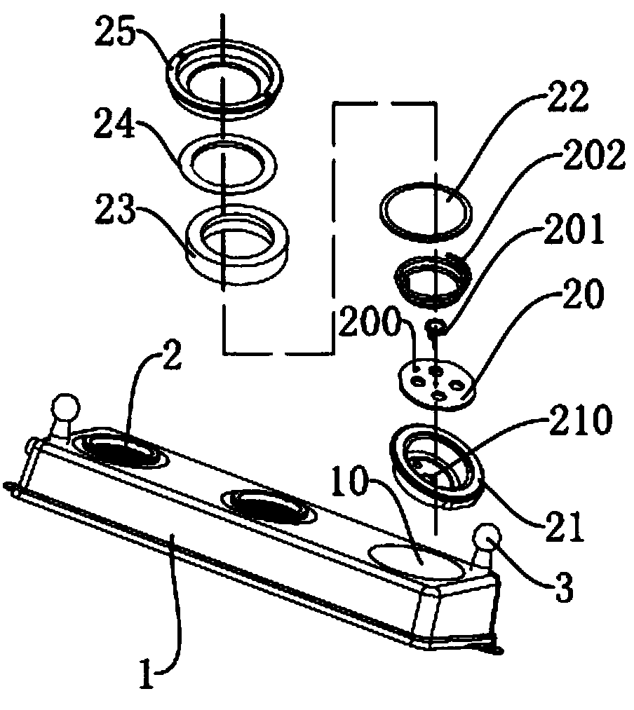
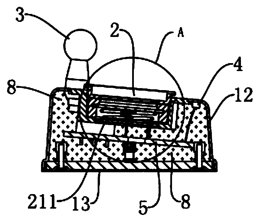
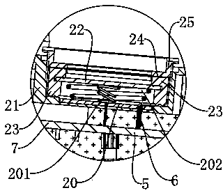
[0025] like figure 1 , figure 2 and image 3 As shown, an ultrasonic atomization generator 2 is a device capable of converting high-frequency electrical energy into mechanical energy and atomizing liquids such as water. It includes a unit housing 21 with a cavity, the unit housing 21 is a member with an upper opening, which can accommodate the insulating plate 20, the transducer sheet 22, the first coil conductive spring 201, the second coil conductive spring and other components 202, sealing ring 23, gasket 24, gland 25, etc. The ultrasonic atomization generator 2 is arranged on an outer casing 1 . The outer casing 1 is provided with three casing holes 10 , and the unit casing 21 is embedded in one of them. The outer casing 1 is also provided with a temperature sensor 4 , an electrical lead 6 ...


PUM


Abstract

An ultrasonic atomization generator comprises a unit shell body provided with a cavity and a transduction sheet contained inside the cavity of the unit shell body. A main electrode layer is arranged on the upper side face of the transduction sheet, a first electrode layer and a second electrode layer which are mutually and electrically isolated are arranged on the lower side face of the transduction sheet, and the second electrode layer is wound on the periphery of the first electrode layer and electrically connected with the main electrode layer. The ultrasonic atomization generator is characterized in that the ultrasonic atomization generator further comprises a first spiral conductive spring and a second spiral conductive spring, the tail end of the first spiral conductive spring and the tail end of the second spiral conductive spring are located inside the cavity, the second spiral conductive spring is wound on the outer side of the first spiral conductive spring and electrically isolated from the first spiral conducive spring, and the top end of the first spiral conductive spring and the top end of the second spiral conductive spring are arranged on the first electrode layer and the second electrode layer respectively and correspondingly in an abutting mode, wherein the first electrode layer and the second electrode layer are arranged on the lower side face of the transduction sheet. Due to the fact that the ultrasonic atomization generator has the characteristics and advantages, the ultrasonic atomization generator can be applied to ultrasonic atomization generator products.

Description

technical field [0001] The present invention relates to an ultrasonic atomizing generator capable of atomizing liquids such as water. Background technique [0002] Ultrasonic atomizers are generally used to atomize liquids such as water in containers. In the prior art, such as the utility model patent with the application number of 200520062411.X, an atomizer with a lamp is disclosed, which is special in that it is mainly composed of a transparent plastic ring with an interlayer, and is located on the outer side of the transparent plastic ring. The metal ring is composed of the ultrasonic vibration plate assembly located in the transparent plastic ring hole, the control circuit board arranged under the ultrasonic vibration plate assembly, and the lamp sealed in the transparent plastic ring interlayer. The ultrasonic vibration plate assembly and the control circuit are formed. An epoxy resin layer is arranged between the boards. Secondly, the patent application also disclos...

Claims


Application Information

Patent Timeline
IPC IPC(8): B05B17/06
CPCB05B17/0646
Inventor 罗杰燊朱勇雄冯锦云
Owner 佛山市科日压电器件有限公司
Why Eureka
Try Eureka