Drawing die

A drawing die and die technology, applied in forming tools, manufacturing tools, metal processing equipment, etc., can solve the problems of easy generation of built-up edge, affect the quality of steel shell, reduce production efficiency, etc., to extend the continuous operation time, The effect of improving deposition phenomenon and improving production efficiency

Active Publication Date: 2014-01-22
无锡金杨丸伊电子有限公司
View PDF5 Cites 4 Cited by
  • Summary
  • Abstract
  • Description
  • Claims
  • Application Information

AI Technical Summary

Problems solved by technology

[0004] The purpose of the present invention is to address the above problems and provide a drawing die to solve the problems that the existing drawing dies are prone to produce built-up edge during use, which affects the quality of the steel shell and reduces the production efficiency.

Method used


Image

  • Drawing die
  • Drawing die
  • Drawing die

Examples


Embodiment Construction

[0017] The technical solutions of the present invention will be further described below in conjunction with the accompanying drawings and through specific implementation methods.

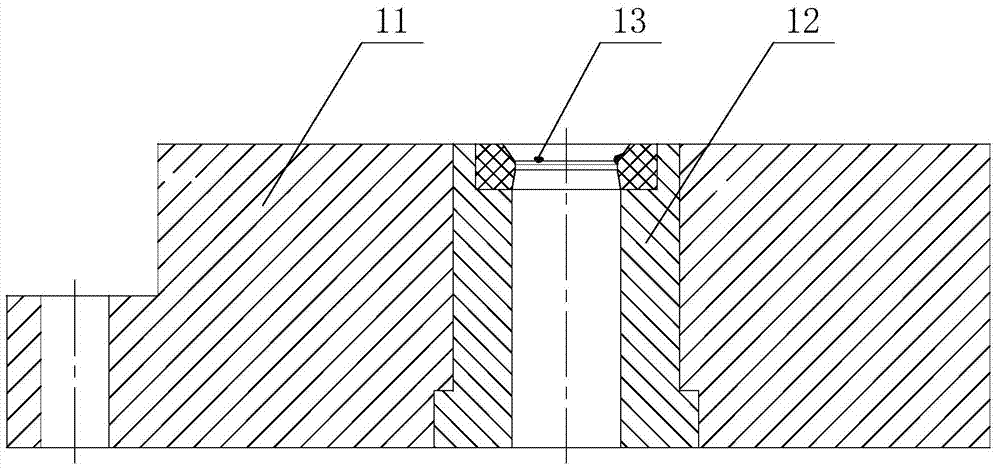
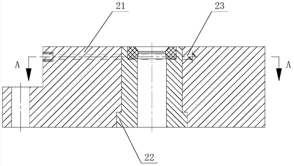
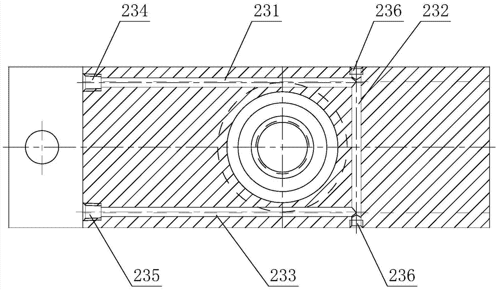
[0018] Please refer to figure 2 and image 3 as shown, figure 2 It is a structural schematic diagram of a stretching die of the present invention; image 3 yes figure 2 A schematic cross-sectional view of a stretching die at A-A is shown. In this embodiment, a drawing die includes a die base 21 and a die 22 disposed in the die base 21, a cooling channel 23 is opened on the die base 21, and the cooling channel 23 is arranged on At the periphery of the mouth of the die 22, the cooling channel 23 includes a liquid inlet pipe 231 and a liquid outlet pipe 233 parallel to each other. One end of the liquid inlet pipe 231 is provided with a liquid inlet 234, and the other end is connected to the connecting pipe. 232 connected, one end of the liquid outlet pipe 233 has a liquid outlet 235, and the ot...


PUM


Abstract

The invention discloses a drawing die. The drawing die comprises a concave die socket and a concave die arranged in the concave die socket, wherein a cooling channel is formed in the concave die socket. According to the drawing die, the cooling channel is additionally formed in the concave die socket so that the concave die socket can be subjected to forced cooling; besides, a water cooling machine is arranged to lower the temperature of cooling water, so that the cooling effect is further enhanced; by the adoption of the concave die socket of the structure, the temperature of the concave die socket only ranges from 20 DEG C to 25 DEG C when the air temperature is 35 DEG C, so that the temperature of the concave die is reduced substantially, the deposition phenomenon of built-up edges is greatly reduced, the frequency of machine halts for die repairing is lowered, the continuous operation time is prolonged, the production efficiency is improved, and output is increased.

Description

technical field [0001] The invention relates to a drawing die. Background technique [0002] The battery steel case is a stamped part that is formed by multiple stretching of a thin plate. Such as figure 1 As shown, it is an existing drawing die for drawing a steel shell, which includes a die base 11 and a die 12. During the drawing process, the die 12 of the drawing die has been bearing huge extrusion force and Rapid sliding friction can generate a large amount of heat, especially at the mouth of the die 12 working section. Although the whole process is lubricated by stretching oil, the high temperature generated at the mouth of the die 12 during stretching will sharply deteriorate the lubrication environment and effect of the steel shell when it passes through this section. The fine particles peeled off from the surface of the shell will gather at the mouth of the die 12 to form a built-up edge 13. The combination of the attached built-up edge 13 and the die 12 is very ...

Claims


Application Information

Patent Timeline
Patent Type & Authority Applications(China)
IPC IPC(8): B21D37/10B21D37/16B21D22/20
Inventor 周勤勇杨建林
Owner 无锡金杨丸伊电子有限公司
Why Eureka
Try Eureka