Clamp for welding multi-sectional thin-wall parts

A thin-walled parts, multi-stage technology, applied in the direction of welding equipment, auxiliary welding equipment, welding/cutting auxiliary equipment, etc., can solve the problems of cost increase, part deformation, long time, etc., to reduce positioning errors, improve efficiency, The effect of preventing part deformation

Active Publication Date: 2014-01-22
四川成发普睿玛机械工业制造有限责任公司
View PDF7 Cites 34 Cited by
  • Summary
  • Abstract
  • Description
  • Claims
  • Application Information

AI Technical Summary

Problems solved by technology

Thus there are the following problems: 1. Due to the need for multiple assembly, errors caused by repeated positioning are unavoidable
2. Due to the thin wall of the parts to be welded, it is easy to cause deformation of the parts during mult...

Method used


Image

  • Clamp for welding multi-sectional thin-wall parts
  • Clamp for welding multi-sectional thin-wall parts
  • Clamp for welding multi-sectional thin-wall parts

Examples


Embodiment Construction

[0038]The structure of the multi-section thin-walled parts welding jig according to the present invention will be further described below by way of embodiments and with reference to the accompanying drawings.

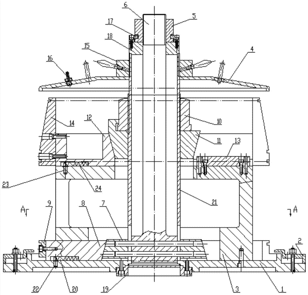
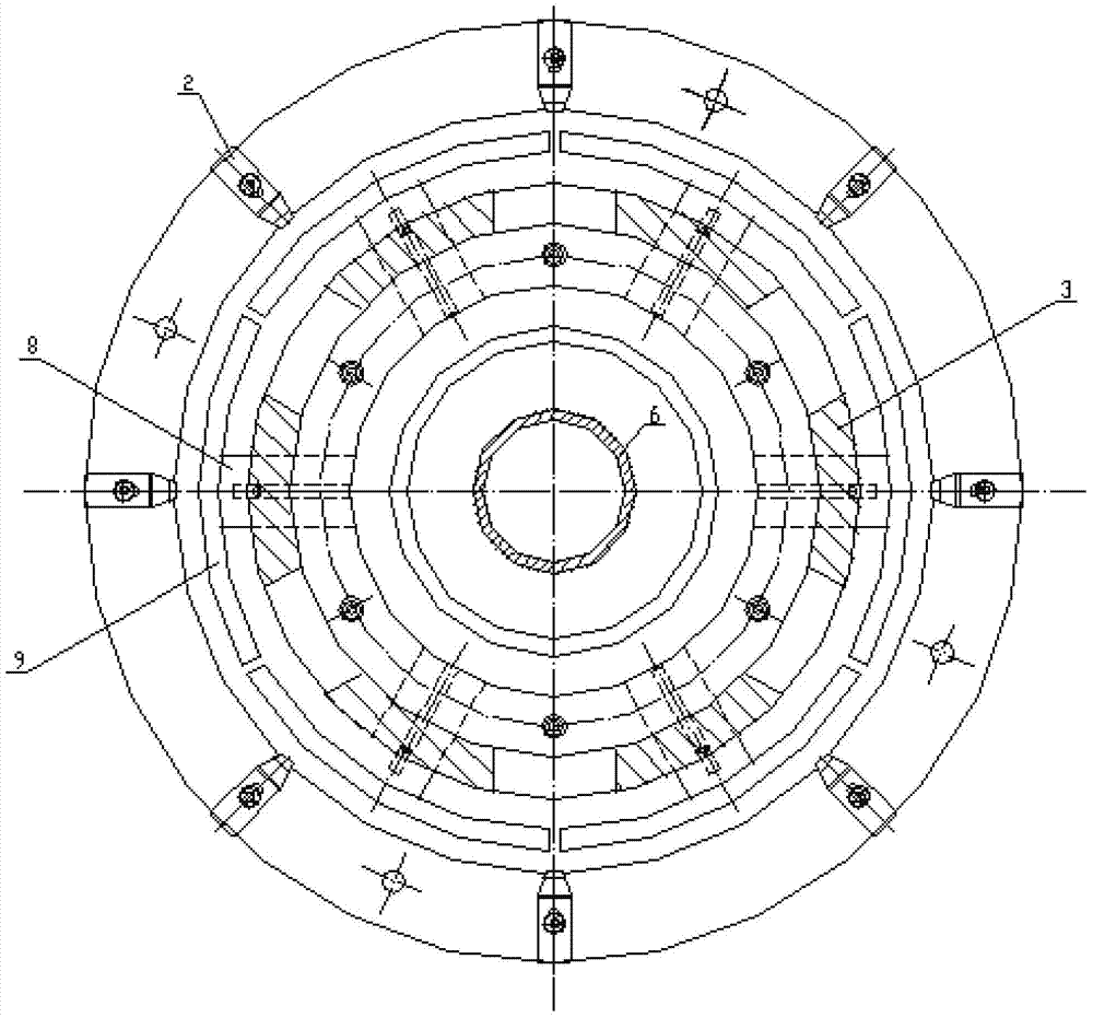
[0039] The multi-segment thin-walled parts welding fixture in this embodiment is used for welding five-segment thin-walled parts with a diameter>600mm, and its structure is as follows figure 1 , figure 2 As shown, it includes base 1, limit ring 3, tie rod 6, first taper mandrel 7, lower block 8, lower block 9, second taper mandrel 11, upper slide block 12, guide block 13, and riser block 14. Short shaft 18, sleeve 21, pressure plate 2, first nut 5, pressure ring 17, second nut 10, welding equipment connecting shaft 19, pressure plate 2, gland 4 and third nut 15.

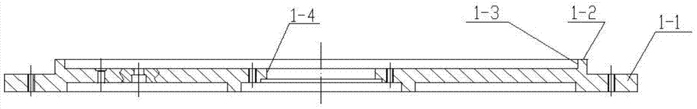
[0040] base 1 as image 3 , Figure 4 As shown, it consists of a truncated conical seat body 1-1 and a circular boss 1-2 arranged on the upper end surface of the seat body. The center of the base 1 is prov...


PUM


Abstract

A clamp for welding multi-sectional thin-wall parts comprises a base, a limit ring, a pull rod, a first taper mandril, a lower slide block, a lower expanding block, a second taper mandril, an upper slide block, a guide block, an upper expanding block, a short shaft, a sleeve, a pressing plate, a first nut, a pressing ring, a second nut, a welding device connection shaft, a pressing plate, a pressing cover and a third nut. By means of the clamp for welding the multi-sectional thin-wall parts, the welding of the multi-sectional thin-wall parts can be achieved by primary assembly and welding.

Description

technical field [0001] The invention belongs to a welding fixture, in particular to a fixture for welding multi-section large thin-walled parts (diameter>600mm). Background technique [0002] Regarding the welding of multi-section large thin-walled parts, the prior art requires multiple sets of fixtures (or tooling), and the welding of all parts is completed in a manner of multiple assembly and multiple welding. For example, if five sections of large thin-walled parts need to be welded together, at least three sets of fixtures (or tooling) are required for three assembly and three welding. Therefore, there are the following problems: 1. Due to the need for multiple assembly, errors caused by repeated positioning inevitably exist. 2. Due to the thin wall of the welded parts, it is easy to cause deformation of the parts during multiple disassembly and assembly processes. 3. Due to the need for multiple assembly and multiple welding, the welding operation takes a long time...

Claims


Application Information

Patent Timeline
IPC IPC(8): B23K37/053
CPCB23K37/053
Inventor 刘建乔惠芳姜宝华吴小兰杨莉玫陈栋权罗仁俊
Owner 四川成发普睿玛机械工业制造有限责任公司
Why Eureka
Try Eureka