Injection molding method of plastic worm wheel and injection mold assembly

A technology of injection molds and worm gears, which is applied to gears, household appliances, and other household appliances. It can solve problems such as high cost, long ring gear cycle, and poor product accuracy, and achieve low cost, short processing cycle, and stable dimensions.

Inactive Publication Date: 2014-01-22
SHENZHEN HISYM IND
View PDF5 Cites 10 Cited by
  • Summary
  • Abstract
  • Description
  • Claims
  • Application Information

AI Technical Summary

Problems solved by technology

This way of manufacturing the ring gear has a long period and high cost
Due to the mechanical deformation caused by the forced ejection of the plastic worm gear, the helix angle and tooth shape of the plastic worm gear will change, and the product accuracy will be poor.

Method used


Image

  • Injection molding method of plastic worm wheel and injection mold assembly
  • Injection molding method of plastic worm wheel and injection mold assembly
  • Injection molding method of plastic worm wheel and injection mold assembly

Examples


Embodiment 1

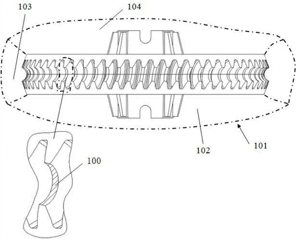
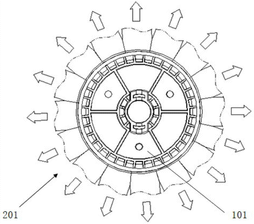
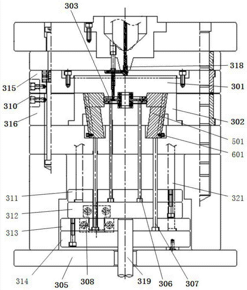
[0041] like Figures 3 to 7 As shown, the lateral sliding mechanism is an inclined top 501, the head of the inclined top is in the shape of fan-shaped teeth, and the two sides of the inclined top head 502 are slopes 503 that cooperate with the adjacent inclined tops, which are arranged in a circle. The slanted top head 502 of the fan-shaped tooth shape of several slanted tops 501, the front mold core 301 of the fixed mold part 401 and the rear mold core 302 of the movable mold part 402 are combined into the mold cavity 303 of the plastic worm wheel mold; The back 504 of 501 is provided with a T-shaped protrusion, and the guide angle of the inclined top 501 is 5°-10° (preferably 8°) away from the center of the cavity 303 relative to the ejection direction of the ejection mechanism; The inclined top 501 is placed in the inclined top guide groove 304, and the inclined top guide groove 304 is provided with a T-shaped groove which is combined with the T-shaped protrusion of the inc...

Embodiment 2

[0048] like Figures 8 to 14 As shown, the lateral sliding mechanism is a slider 106, the head of the slider 106 is in the shape of a fan-shaped tooth, and the two sides of the slider head 107 are slopes matching with adjacent sliders, and several sliders arranged in a circle The slider head 107 of the fan-shaped tooth shape of the block, the front mold core 301 of the fixed mold part 401 and the rear mold core 302 of the movable mold part 402 are combined to form the cavity 303 of the plastic worm gear mold; the slide block 106 is placed In the slider guide groove 801, the slider guide groove 801 leaves a space for the slider 106 to slide; the middle part of the slider is provided with an oblique groove 110, and the oblique groove 110 extends away from the top of the slider. The center of the cavity 303 extends to the inside of the slider 106 ; the lower end of the front mold core 301 of the fixed mold part 401 is fixed with a locking block 802 that fits with the oblique groo...


PUM


Abstract

The invention provides an injection molding method of a plastic worm wheel and an injection mold assembly. The injection mold assembly comprises a fixed mold part and a movable mold part, and the movable mold part comprises a plurality of circumferentially-arranged lateral sliding mechanisms and an ejection mechanism. The end portions, close to a circle center, of the lateral sliding mechanisms are in a fan-shaped tooth shape, and the fan-shaped tooth end portions of the lateral sliding mechanisms, the front mold cavity of the fixed mold part and the rear mold cavity of the movable mold part form the mold cavity of a plastic worm wheel mold. In the demolding process, the lateral sliding mechanisms laterally slide to be separated from the plastic worm wheel, the ejection mechanism arranged on the movable mold part ejects out the plastic worm wheel, and the finished product of the plastic worm wheel is obtained. An injection mold is simple in structure, the machining method of the injection molding method of the injection mold is diversified, the precision of a mold part is easy to control, the machining period is short, cost is low, and above all, large-batch production can be achieved on an injection molding machine, product precision is high, and the size is stable.

Description

technical field [0001] The invention relates to an injection mold assembly and an injection molding method, in particular to an injection molding method of a plastic worm gear and an injection mold assembly. Background technique [0002] Plastic worm gears are widely used in modern industry. Plastic worm gears are often paired with worms to transmit motion and power between two staggered shafts. The worm gear mechanism has the characteristics of large bearing capacity, large transmission ratio and axial force, compact structure, stable transmission, small vibration, and self-locking function. [0003] At present, the manufacture of plastic worm gears is mainly realized in the following three ways: [0004] 1. Use the worm gear hob to process on the gear hobbing machine. The worm gear hob needs to be customized according to the parameters of the plastic worm gear. The precision requirements for the machine tool for manufacturing the hob and processing the plastic worm gear a...

Claims


Application Information

Patent Timeline
Patent Type & Authority Applications(China)
IPC IPC(8): B29C45/33B29C45/40
CPCB29C45/4435B29C45/33B29L2015/00
Inventor 张海臣周庆胜
Owner SHENZHEN HISYM IND
Why Eureka
Try Eureka