Track vehicle steering frame

A rail vehicle and bogie technology, applied in the field of bogies, can solve problems such as high cost and complex structure, and achieve the effects of simple manufacturing process, complex structure and reduced impact

Active Publication Date: 2014-01-22
CRRC TANGSHAN CO LTD
View PDF7 Cites 21 Cited by
  • Summary
  • Abstract
  • Description
  • Claims
  • Application Information

AI Technical Summary

Problems solved by technology

[0005] The invention provides a rail vehicle bogie to solve the problem that the rail vehicle bogie in the prior art adopts a suspension device composed of an air spring and corresponding components, resulting in complex structure and high cost

Method used


Image

  • Track vehicle steering frame
  • Track vehicle steering frame
  • Track vehicle steering frame

Examples


Embodiment 1

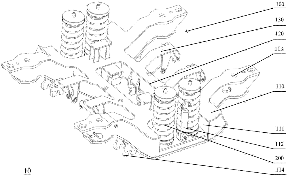
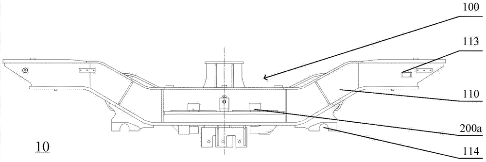
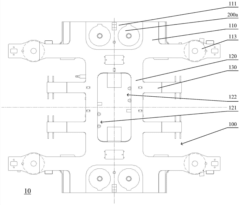
[0031] figure 1 It is a schematic structural diagram of a rail vehicle bogie provided in Embodiment 1 of the present invention, figure 2 for figure 1 Front view of the frame in the shown rail vehicle bogie, image 3 for figure 1 Top view of frame in rail vehicle bogie shown. Please refer to figure 1 , figure 2 and image 3 , the railway vehicle bogie 10 provided by the present embodiment includes: a frame 100 and a secondary suspension device 200; Two beams 120 are arranged in parallel and spaced between two side beams 110, and the side beams 110 are perpendicular to the beams 120; two brake suspension beams 130 are arranged on each beam 120 at parallel intervals; the brake suspension beams 130 is parallel to the side beams 110, and the middle groove 111 of each side beam 110 is provided with a mounting seat 200a; the secondary suspension device 200 includes a plurality of steel springs, and the multiple steel springs are respectively symmetrically arranged on the two...

Embodiment 2

[0037] Figure 4 It is a structural schematic diagram of a traction device in a rail vehicle bogie provided by Embodiment 2 of the present invention. Please refer to image 3 and Figure 4 , the railway vehicle bogie 10 provided in this embodiment also includes: a traction device 300, which includes: a central pin 310, a traction beam 320 and a traction rod 330, the upper end of the central pin 310 is a plate-shaped structure, and the lower end is inserted into the traction Inside the beam 320, one end of the traction rod 330 is connected to the traction beam 320, and the other end is connected to the crossbeam 120; The relative operation drives the frame 100 to move, so that the railway vehicle bogie 10 can move in a straight line and in a curve under the traction force of the traction device 300 .

[0038] Preferably, in the specific implementation of this embodiment, the above-mentioned traction rods 330 may be two, and they are arranged obliquely and symmetrically on bo...

Embodiment 3

[0040] Figure 5 It is a top view of a wheel set and axle box positioning device in a rail vehicle bogie provided by Embodiment 3 of the present invention, Image 6 for Figure 5 Left side view of the wheelset and axlebox positioning device in the rail vehicle bogie shown. Please refer to figure 2 , Figure 5 and Image 6 , the railway vehicle bogie 10 provided in this embodiment also includes: two wheel sets 410 and four axle box positioning devices 420, the four axle box positioning devices 420 are respectively arranged at the two ends of the two side beams 110 and located at the wheel On the outside of 410; each axle box positioning device 420 includes a rotating arm 421 and a series of suspension devices 422, and the two ends of each side beam 110 are provided with cap tubes 113, and one end of the rotating arm 421 is connected to the bottom of the side beam 110; One end of the primary suspension device 422 is arranged on the upper part of the rotating arm 421 , and ...


PUM


Abstract

The invention provides a track vehicle steering frame which comprises a framework and a secondary suspension device. The framework comprises two side beams, two horizontal beams and four braking hanging beams. The two side beams are arranged in parallel at intervals. The two horizontal beams are arranged between the two side beams in parallel at intervals. The side beams are perpendicular to the horizontal beams. Two braking hanging beams are arranged on each horizontal beam in parallel at intervals. The braking hanging beams and the side beams are parallel. A mounting base is arranged at a middle groove of each side beam. The secondary suspension device comprises a plurality of steel springs which are symmetrically arranged on the mounting bases at the middle grooves of the two side beams respectively. The track vehicle steering frame solves the problem that in the prior art, a suspension device of a track vehicle steering frame is formed by an air spring and corresponding components, so that structure is complex, and cost is high.

Description

technical field [0001] The invention relates to bogie technology, in particular to a rail vehicle bogie. Background technique [0002] With the improvement of the capacity of rail vehicles, rail vehicles have become the main means of transportation for people to travel. As one of the most important components in the structure of rail vehicles, the bogie structure directly determines the stability of the vehicle and the comfort of the vehicle. [0003] The bogie of rail vehicles is mainly used to bear the weight of the car body and ensure the safe operation of the vehicle, so that the vehicle can flexibly run along the straight line and pass the curve smoothly; the structure of the commonly used bogie mainly includes: frame, axle box , safety wire ropes, height valves, air springs, torsion bars, wheels, axles, traction center pins, lateral shock absorbers, lateral stops, differential pressure valves, air pipeline devices, etc.; among them, the bogie used to support the car bo...

Claims


Application Information

Patent Timeline
Patent Type & Authority Applications(China)
IPC IPC(8): B61F5/00B61F5/06B61H11/06
Inventor 李得花李建锋赵家明杨永勤张隶新
Owner CRRC TANGSHAN CO LTD
Why Eureka
Try Eureka