Idler wheel switch blade chain pulling device and manufacturing and installing technology of idler wheel switch blade chain pulling device

The technology of a knife chain catcher and roller, which is applied in the field of ship anchors, can solve the problems of large structural type of the chain catcher body, inaccurate cutting, friction between the anchor chain and the roller gate knife chain catcher, etc., so as to reduce the work of the berth The effect of reducing the amount and waste return, avoiding secondary cutting, and shortening the shipbuilding cycle

Active Publication Date: 2014-01-22
WUCHANG SHIPBUILDING IND
View PDF9 Cites 3 Cited by
  • Summary
  • Abstract
  • Description
  • Claims
  • Application Information

AI Technical Summary

Problems solved by technology

During the design and manufacture of the roller gate knife chain control device, a cutting allowance for installation on board is left when the components of the chain control device are unloaded in the infield, so that the construction personnel on site can continue to try when installing and positioning the roller gate knife chain control device. Install and adjust the positioning, so that the inclination angle α between the roller gate knife chain device and the deck meets the design requirements, and meets the requirements of no chain rubbing, no chain overturning, and no chain jumping. Insufficient actual margin at the welding joint of the base of the roller gate knife chain device, or a large amount of on-site cutting, inaccurate cutting, long installation period, and low installation efficiency, etc.
Moreover, during the actual processing, manufacturing and installation process, it was found that the structure of the chain stopper body was too large. When retracting and releasing the anchor chain, it was easy to cause the anchor chain to collide with the roller brake knife chain stopper. low defect

Method used


Image

  • Idler wheel switch blade chain pulling device and manufacturing and installing technology of idler wheel switch blade chain pulling device
  • Idler wheel switch blade chain pulling device and manufacturing and installing technology of idler wheel switch blade chain pulling device

Examples


Embodiment Construction

[0016] The technical solutions of the present invention will be further specifically described below in conjunction with the accompanying drawings and specific embodiments.

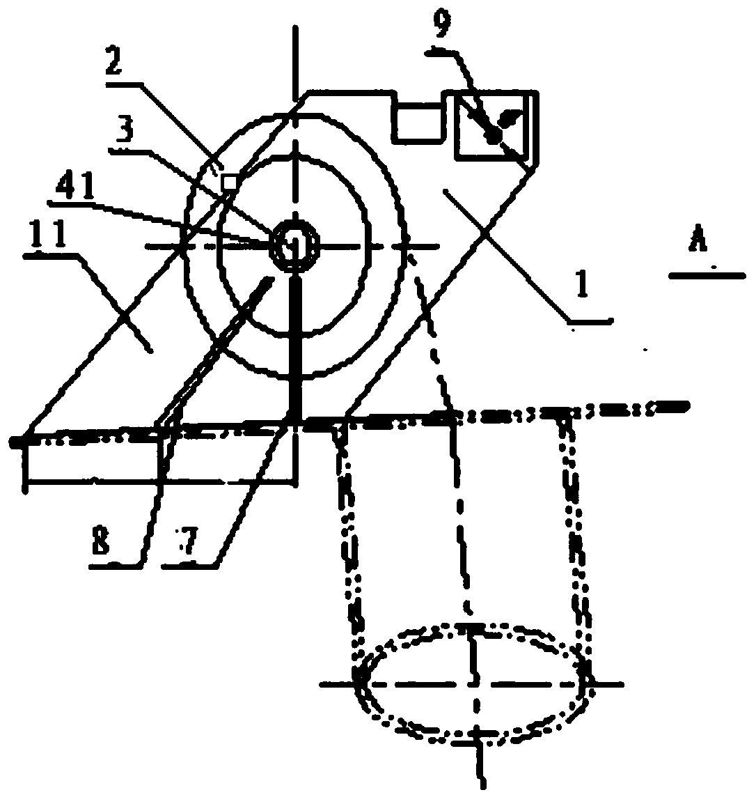
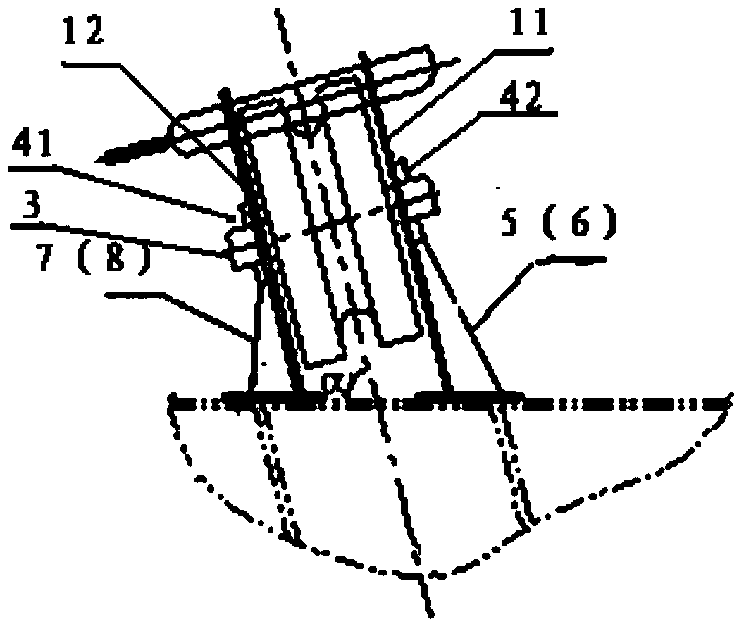
[0017] In the construction of a cruise ship, the roller brake knife chain device was chosen, such as figure 1 and figure 2 As shown, the roller brake knife chain device includes a roller 2 installed in the body 1, and a roller shaft 3 is arranged inside the roller 2, and the two ends of the roller shaft 3 pass through the left and right side plates of the body with left bushings 41 respectively. , the right bushing 42 is fixed, and the first toggle plate 5 and the third toggle plate 6 are also installed on the outside of the left side plate 11 of the body, and the second toggle plate 7 and the third toggle plate are also installed on the outside of the right side plate 12 of the body. Four toggle plates 8; the first toggle plate 5 and the second toggle plate 7 are located on the vertical plane of the ax...


PUM


Abstract

The invention discloses an idler wheel switch blade chain pulling device. A first bracket and a second bracket of the idler wheel switch blade chain pulling device are located on the vertical plane of the axial lead of an idler wheel, the upper end of the lateral side of a third bracket is located below a left lining, the upper end of the lateral side of a fourth bracket is located below a right lining, the lateral side of the first bracket and the lateral side of the third bracket are respectively connected with a left side plate of a body in a welded mode, and the lateral side of the second bracket and the lateral side of the fourth bracket are connected with a right side plate of the body in a welded mode. Parts of the idler wheel switch blade chain pulling device are assembled in place in an internal field according to designed sizes, the four brackets are welded on the body of the idler wheel switch blade chain pulling device, and one-step installation can be achieved when the idler wheel switch blade chain pulling device is installed on a slipway. According to the idler wheel switch blade chain pulling device, the four brackets are additionally installed, the dip angle alpha between the idler wheel switch blade chain pulling device and a deck is directly determined, the sizes of the parts of the idler wheel switch blade chain pulling device are directly determined at one time in the internal field, the manufacturing accuracy of the parts is improved, and the ship building cost is reduced.

Description

technical field [0001] The invention belongs to the technical field of ship anchors, and in particular relates to a roller brake knife chain stopper and its manufacturing and installation process. Background technique [0002] Usually, the structural type of the chain stopper is based on the ship type, the type and standard selection configuration between the windlass and the anchor chain barrel. , and finally enter the chain locker to decide which structural type of chain stopper to choose. The roller brake knife chain stopper is a relatively common type of chain stopper at present. It is designed and manufactured according to the ship industry standard CB / T3844-2000. It includes a roller installed in the body. There is a roller shaft inside the roller. The left and right side panels of the main body are fixed with bushings. During the design and manufacture of the roller gate knife chain control device, a cutting allowance for installation on board is left when the compo...

Claims


Application Information

Patent Timeline
Patent Type & Authority Applications(China)
IPC IPC(8): B63B21/18B23K31/02
Inventor 刘波姜惠
Owner WUCHANG SHIPBUILDING IND
Why Eureka
Try Eureka