High-frequency coil lifting gear with balance weight part

A high-frequency coil and lifting device technology, which is applied to cranes and other directions, can solve problems such as unreasonable stress on the high-frequency coil lifting mechanism, coil positioning deviation, workpiece heating, high-frequency coil tilting, etc., to achieve convenient and safe use of equipment, reduce Small inertial impact, prolonging the service life

Active Publication Date: 2014-01-22
CHENGDU XUGUANG ELECTRONICS
View PDF8 Cites 4 Cited by
  • Summary
  • Abstract
  • Description
  • Claims
  • Application Information

AI Technical Summary

Problems solved by technology

[0004] In the prior art, the following problems will occur: 1. The force condition of the high-frequency coil lifting mechanism is unreasonable. The high-frequency coil weighs about 30-40Kg, and is fixed on the slider through an insulating plate and a lifting vertical plate. Such a structure The slider not only bears the gravity of the coil, but also bears the moment generated by the gravity of the high-frequency coil
2. The slider is easy to wear, causing the high-frequency coil to tilt and collide with the workpiece
3. When the high-frequency coil is lowered in place, due to the action of the torque, there will be an inertial impact phenomenon, causing the coil positioning deviation to affect the heating of the workpiece

Method used


Image

  • High-frequency coil lifting gear with balance weight part

Examples


Embodiment Construction

[0015] In order to make the object, technical solution and advantages of the present invention clearer, the present invention will be further described in detail below in conjunction with the accompanying drawings.

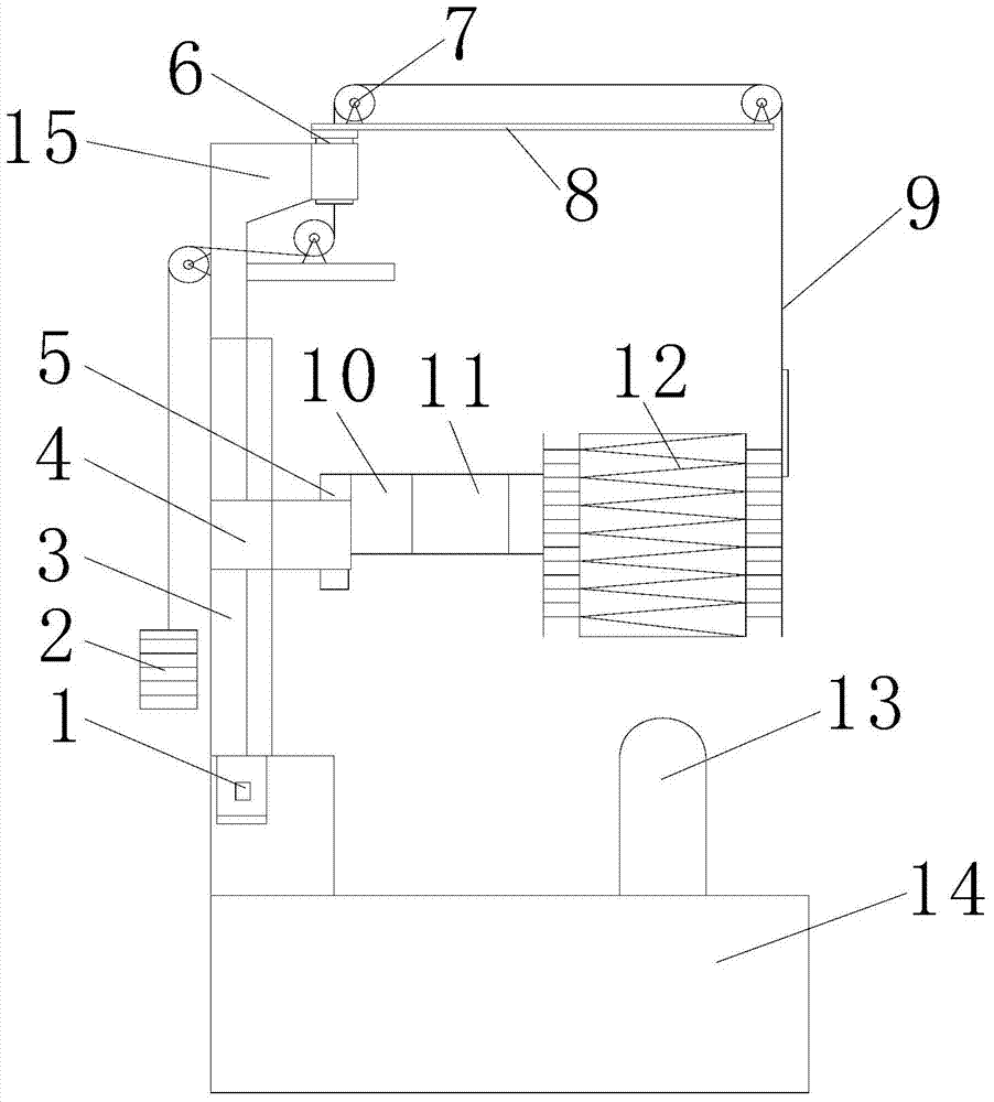
[0016] Such as figure 1 As shown, the present invention is a high-frequency coil lifting device with a counterweight, including a base platform 14, a column 3, the column 3 is fixed on the base platform 14, and the column 3 is provided with a lifting slider 4, and the lifting slider 4 is connected There is a driving motor 1, and the lifting slider 4 is vertically connected with a lifting vertical plate 10 through the vertical plate rotating shaft 5, and the lifting vertical plate 10 is connected with a high-frequency coil 12 through an insulating plate 11, and the top of the column 3 is provided with a counterweight support 15, and the counterweight The support 15 is connected to the counterweight beam 8 through the beam shaft 6, the beam shaft 6 is a hollow shaft...


PUM


Abstract

The invention relates to a machining device, and discloses a high-frequency coil lifting gear with a balance weight part. The high-frequency coil lifting gear comprises a base platform and an upright column. The upright column is fixed on the base platform and provided with a lifting slide block which is connected with a drive motor, the lifting slide block is vertically connected with a lifting vertical plate through a vertical plate rotation shaft, and the lifting vertical plate is connected with a high-frequency coil through an insulation plate. The top end of the upright column is provided with a balance weight support which is connected with a balance weight beam through a beam rotation shaft, and balance weights are connected between the high-frequency coil and pulleys arranged on the balance weight beam and the upright column through drag ropes. The high-frequency coil lifting gear is simple in structure, force bearing conditions of the high-frequency coil are greatly improved, the service life of the slide block and the motor is prolonged, the moving range of the high-frequency coil on the platform is enlarged, inertia impact of the coil in the falling process is reduced, the inclination phenomenon of the high-frequency coil due to long-term lifting is avoided, and operators can conveniently and safely use a device.

Description

technical field [0001] The invention relates to a mechanical processing device, in particular to a high-frequency coil lifting device with a counterweight. Background technique [0002] The high-frequency coil is an important part of the high-frequency vacuum annealing furnace equipment. During the use of the equipment, the coil needs to be lifted and lowered vertically. Due to the special working principle of the high-frequency vacuum annealing furnace, when the coil is loaded with high-frequency current, a strong magnetic field is also generated around the coil, and the metal material close to the coil generates leakage current and heat in the magnetic field, which directly affects the heating temperature of the equipment . Therefore, the high-frequency heating coil and the lifting mechanism cannot be directly connected, and the middle is separated by an insulating material. [0003] In the existing heating equipment, the high-frequency coil is connected to the lifting v...

Claims


Application Information

Patent Timeline
Patent Type & Authority Applications(China)
IPC IPC(8): B66C23/62B66C23/72
Inventor 刘军祝健王正甫高仕勇杨林春
Owner CHENGDU XUGUANG ELECTRONICS
Why Eureka
Try Eureka