
Top electrode of reaction tank device for etching equipment

A technology of etching equipment and reaction tank, applied in the field of electrodes, can solve the problems of ceramic spray film peeling, high thermal expansion coefficient, low thermal expansion coefficient, etc., and achieves the effect of reducing equipment cost, not easy to peel off, and tightly combined

Inactive Publication Date: 2014-01-22
CHOU YEH INVESTMENT CO LTD
View PDF7 Cites 2 Cited by
  • Summary
  • Abstract
  • Description
  • Claims
  • Application Information

AI Technical Summary

Problems solved by technology

[0005] Although the said No. M396828 patent has the above-mentioned advantages and effects, it still has room for improvement, mainly because the material of the electrode plate is metal with a high coefficient of thermal expansion, while the material of the ceramic spray film is ceramics with a relatively high coefficient of thermal expansion. Low
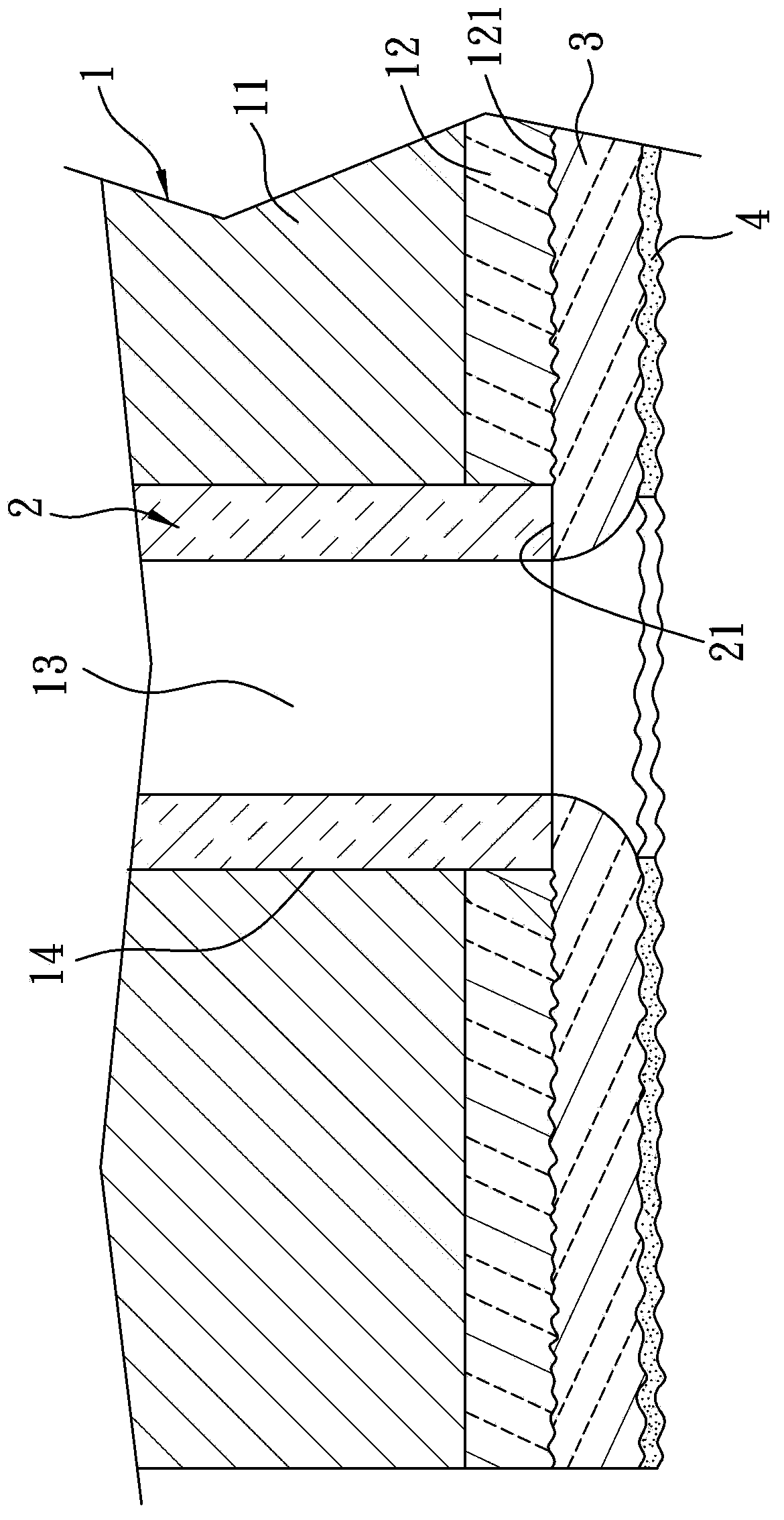
That is to say, there will be an obvious interface between the electrode plate body and the ceramic fusion film due to the difference in thermal expansion coefficient, and when the temperature rises or falls, the interface tends to accumulate stress due to uneven expansion, resulting in this Cracks and pores are generated at the interface between the ceramic spray film and the electrode plate body, and the adhesion between the ceramic spray film and the electrode plate body is reduced
[0006] Therefore, when the corrosive gas passes through the vent holes of the upper electrode, the corrosive gas will pass through the aforementioned cracks and pores to erode the electrode plate at the interface, and cause the ceramic fusion film to be unable to communicate with The electrode plate body is combined and peeled off, which reduces the protective effect, so the structure of the existing upper electrode still needs to be improved

Method used


Image

  • Top electrode of reaction tank device for etching equipment
  • Top electrode of reaction tank device for etching equipment
  • Top electrode of reaction tank device for etching equipment

Examples


Embodiment Construction

[0023] The present invention will be described in detail below in conjunction with the accompanying drawings and embodiments.

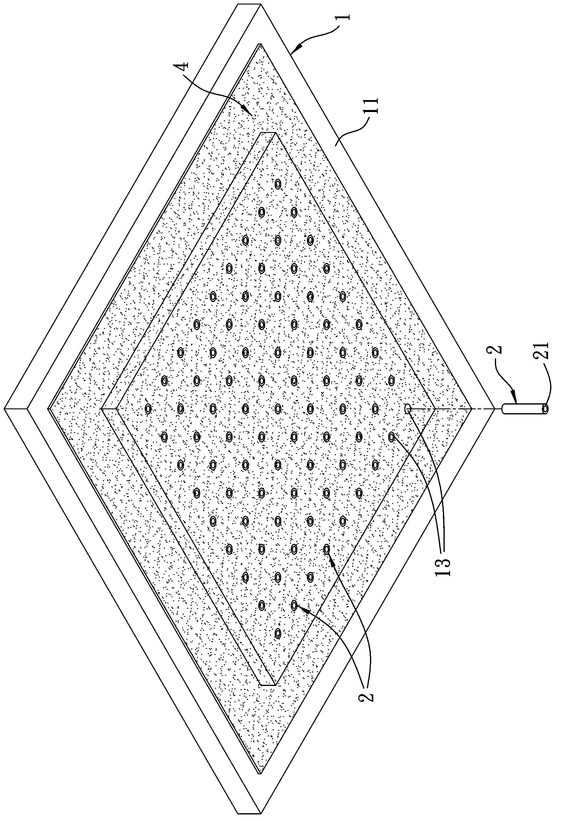
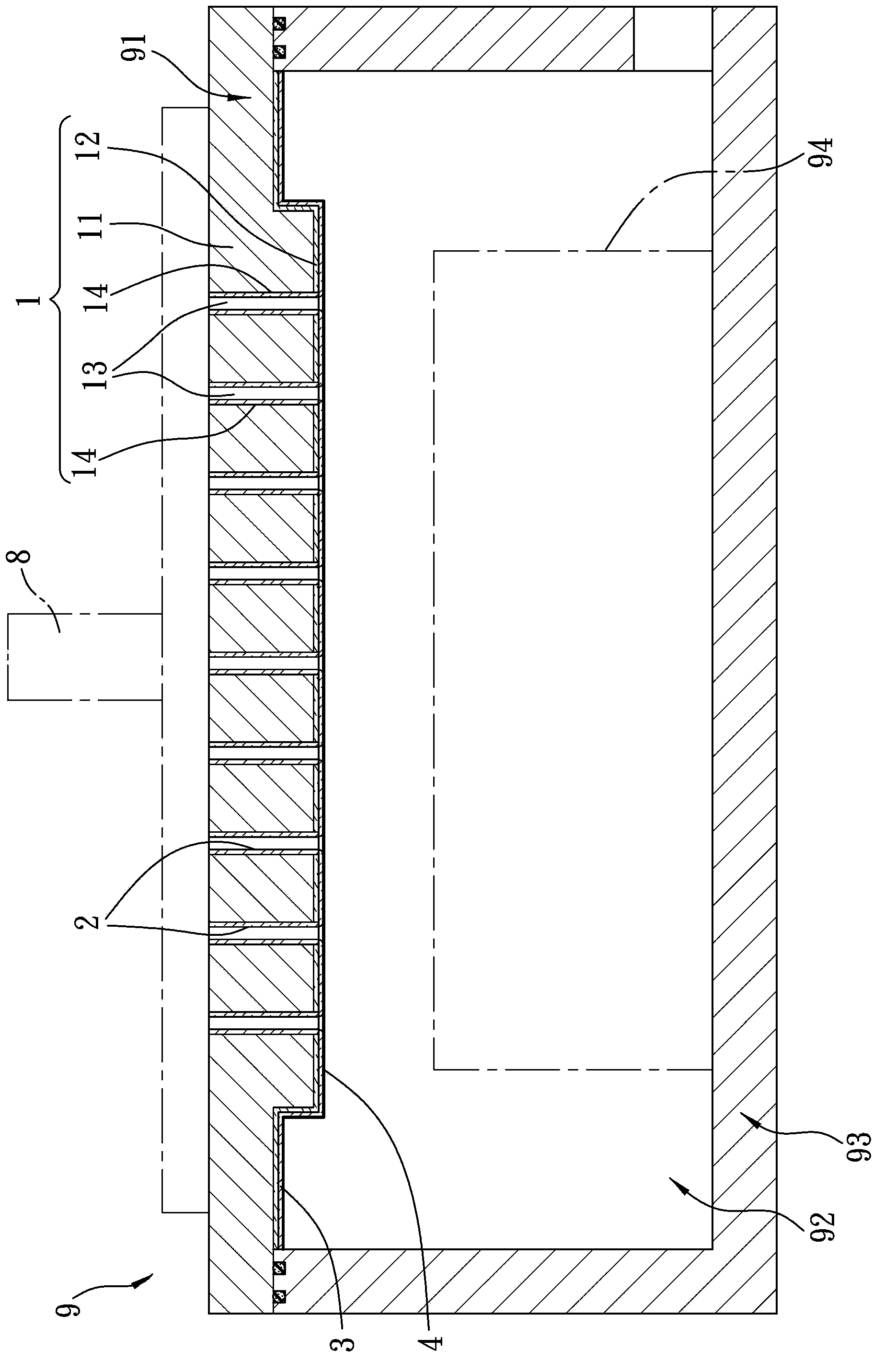
[0024] refer to figure 1 , 2 , 3, a preferred embodiment of the upper electrode 91 of the present invention is one of the components of a reaction tank device 9 of an etching device, and the reaction tank device 9 also includes a reaction chamber that defines a reaction space 92 with an opening facing upwards Seat 93, and a lower electrode 94 installed in the reaction space 92. The upper electrode 91 communicates with a gas input device 8, so that the gas input device 8 can introduce a corrosive gas for etching glass into the reaction space 92, and the corrosive gas can be fluorine or chlorine. Since the operation of the reaction tank device 9 is not the focus of the improvement of the present invention, it will not be described in detail.

[0025] The upper electrode 91 of the present invention is covered on the reaction chamber seat 93 and can be...


PUM

PropertyMeasurementUnit
thicknessaaaaaaaaaa
surface roughnessaaaaaaaaaa
thicknessaaaaaaaaaa

Abstract

The invention discloses a top electrode of a reaction tank device for etching equipment. The top electrode comprises an electrode plate and a ceramic spray film. The electrode plate comprises a body layer, a buffer layer arranged on the body layer, and multiple vent holes which penetrate through the body layer and the buffer layer. The difference of thermal expansion coefficients of the body layer and the ceramic spray film is buffered through the buffer layer, and high binding force exists between the buffer layer and the ceramic spray film, so the buffer layer and the ceramic spray film can be tightly bound and difficultly drop. Meanwhile, the buffer layer and the ceramic spray film have good anti-corrosion effects so as to provide dual protection for the body layer, so that the electrode plate can be repeatedly used, and the equipment cost can be reduced.

Description

technical field [0001] The invention relates to an electrode, in particular to an upper electrode of a reaction tank device of an etching device. Background technique [0002] In the general plasma etching process, the upper electrode is located above the glass substrate and must have high plasma resistance. A layer of anodic film is produced on the surface, such as the patent case No. 88107375 of Taiwan, China. [0003] However, active corrosive gases such as fluorine (F) and chlorine (Cl) used in the plasma etching process will corrode the anode film and cause the upper electrode to fail, so the damaged anode film must be removed first by chemical etching , and then re-grow the anode film, but the aforementioned regeneration method will cause the electrode plate of the upper electrode to become thinner. When the thickness of the electrode plate is too thin to be used, it is necessary to replace the upper electrode with a new one. Therefore, the higher cost. [0004] In ...

Claims


Application Information

Patent Timeline
Patent Type & Authority Applications(China)
IPC IPC(8): C03C15/00
Inventor 周峙丞唐国樑吴建德
Owner CHOU YEH INVESTMENT CO LTD
Learn More