
Water jet propulsion pump

A technology of water jet propulsion and pump body, which is applied in the direction of ship propulsion, propulsion parts, pumps, etc. It can solve the problems of strong gear mesh vibration, power source erosion and water immersion, position deviation, etc., to ensure working noise and high efficiency and long life effect

Inactive Publication Date: 2014-01-22
HUAZHONG UNIV OF SCI & TECH +2
View PDF8 Cites 9 Cited by
  • Summary
  • Abstract
  • Description
  • Claims
  • Application Information

AI Technical Summary

Problems solved by technology

As the water-jet propulsion pump that has been used till now, the above-mentioned pump body can meet the use requirements within a certain range of current boats. However, due to the power source of the above-mentioned pump body, it uses a mechanical seal and a mechanical gear power transmission method, which produces The following problems: First, as a boat component, its own working noise should be reduced as much as possible, and the defect of mechanical gear transmission is that its working noise is relatively large and the vibration of the gear mesh is strong, and the necessary lubrication and maintenance requirements are relatively large. These are all fundamental flaws of gear transmission; secondly, the current structure of the water jet propulsion pump as mentioned above can only be applied to boats on the water surface or shallow water layer, and cannot be applied to high-pressure working environments such as deep-water submarines at all. The root of the use of boats lies in the sealing defects caused by the mechanical gear transmission parts and the mechanical seal structure; in the high-pressure working environment, the water pressure accumulates in the pump chamber and is difficult to dissipate, and it is easy to squeeze the pump. The soft sealing part between the cavity and the power source will compress and eventually reduce the sealing effect or even fail, which will lead to erosion and water damage to the power source, which will greatly restrict the scope of application of the water jet propulsion pump and reduce the its actual use market
In addition, the installation method of the current water jet propulsion pump for the pump shaft is either fixed by the cantilever beam fixed at one end of the pump shaft as mentioned above, or directly added water lubrication at the front guide vane on the basis of the original cantilever beam fixed. Bearing components, thus forming a simply supported beam structure; the above-mentioned pump shaft cantilever beam fixing method, its working stability is inevitably insufficient, and the actual use is highly restricted, while the simply supported beam structure of the pump shaft, of course, has high working reliability. However, under the action of water pressure, the high-pressure liquid medium located on the nozzle side of the pump body will not only lubricate the water-lubricated bearing assembly on the front guide vane, but also affect the entire water-lubricated bearing assembly and even the entire water-lubricated bearing assembly along the lubrication gap of the water-lubricated bearing assembly. The front guide vane generates water thrust, and under long-term action, it is easy to cause positional deviation between the above-mentioned components in the original installation position along the thrust direction, and eventually the product assembly will be loosened or even damaged, thus giving Maintenance staff cause great trouble

Method used


Image

  • Water jet propulsion pump
  • Water jet propulsion pump

Examples


Embodiment Construction

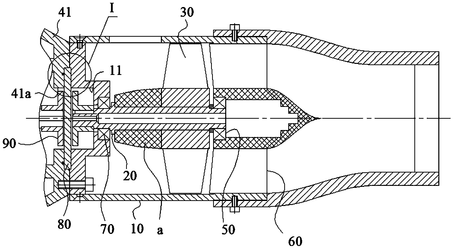
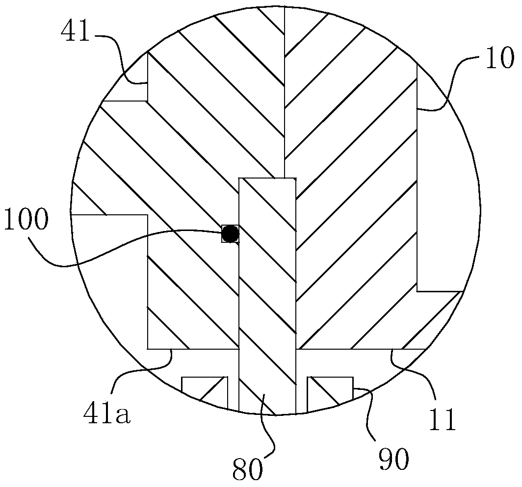
[0028] For ease of understanding, combine here Figure 1-2 The overall assembly components and work flow of the water jet propulsion pump are described as follows:

[0029] Such as figure 1 The structure of the water jet propulsion pump shown has a hollow straight barrel-shaped pump body 10 as its main body shell, in which a pump shaft 20 is arranged, and the axis of the pump shaft 20 is arranged coaxially with the axis of the pump body 10; the length of the pump shaft 20 is shorter than that of the pump The length of the body 10; one end of the pump shaft 20 and the bottom surface of the barrel of the pump body 10 form a rotation, that is, a bearing matching structure, to form the power end of the pump shaft 20, and the other end of the pump shaft 20 extends along its axis and is similar to the front guide The bearing assembly 50 at the shaft of the blade 60 forms a bearing fit, thereby forming a simply supported beam fixed structure relative to the pump shaft 20. The power sou...


PUM


Abstract

The invention belongs to the field of pumps and particularly relates to a water jet propulsion pump which comprises a pump body and a pump shaft assembly arranged at a pump cavity of the pump body. The pump shaft assembly at least comprises a pump shaft and an impeller wheel arranged on the pump shaft; the pump shaft is of a simply supported beam structure with bearings at the two ends of the pump shaft fixedly connected, the tail end of the pump shaft and a power source of the water jet propulsion pump are in normal-running fit, and the head end of the pump shaft extends in the axial direction and is in bearing fit with a bearing assembly arranged on the pump body; bounded by an impeller wheel body, the water jet propulsion pump is divided into a water inlet area and a water outlet area, wherein the water inlet area is communicated with a liquid inlet of the pump body, and the water outlet area is used for discharging water; a reflux passageway used for reducing the hydraulic thrust at the bearing assembly is arranged between the water inlet area and the water outlet area, and the water inlet area of the pump body, the water outlet area of the pump body, gaps to be lubricated of the bearing assembly and the reflux passageway are sequentially communicated and form a circular flow channel. The water jet propulsion pump is reasonable and practical in structure, wide in working usage range and long in service life, and high-efficiency work of components within the whole water outlet area of the pump body can be effectively guaranteed.

Description

Technical field [0001] The invention belongs to the field of pumps, and specifically relates to a water jet propulsion pump. Background technique [0002] The water jet propulsion device is a ship propulsion structure that uses the reaction force of the water pump to spray the water behind the ship to make the boat move forward. The water jet propulsion pump is one of the main components of the water jet propulsion device. After the water jet propulsion device is applied to the boat equipment, it can make the boat have a series of advantages such as small turning radius, low noise and vibration in the cabin, simple structure, low shallow water effect, and easier daily maintenance and maintenance. Boats, wave piercing craft, hydrofoil craft, hovercraft and other medium and high-speed ships and even submarines have been widely used. [0003] The specific structure of the water jet propulsion pump is described in the Chinese invention patent application with the announcement number: ...

Claims


Application Information

Patent Timeline
IPC IPC(8): F04D29/52F04D29/043F04D13/02B63H11/08
Inventor 李宝仁何玉杰李强李跃柴立平巫建波石海峡高磊王秀兰
Owner HUAZHONG UNIV OF SCI & TECH
Learn More