Magneto-rheological damper suitable for high-speed impact/low-speed vibration control system

A magneto-rheological damper and vibration control technology, applied in the direction of vibration suppression adjustment, non-rotational vibration suppression, etc., can solve problems such as stretching, and achieve the effect of increasing the shear area, increasing the range of controllable damping ratio, and simple structure

Active Publication Date: 2014-01-22
HEFEI UNIV OF TECH
View PDF8 Cites 27 Cited by
  • Summary
  • Abstract
  • Description
  • Claims
  • Application Information

AI Technical Summary

Problems solved by technology

But for the application requirements of higher speed-controlla

Method used


Image

  • Magneto-rheological damper suitable for high-speed impact/low-speed vibration control system
  • Magneto-rheological damper suitable for high-speed impact/low-speed vibration control system
  • Magneto-rheological damper suitable for high-speed impact/low-speed vibration control system

Examples


Embodiment Construction

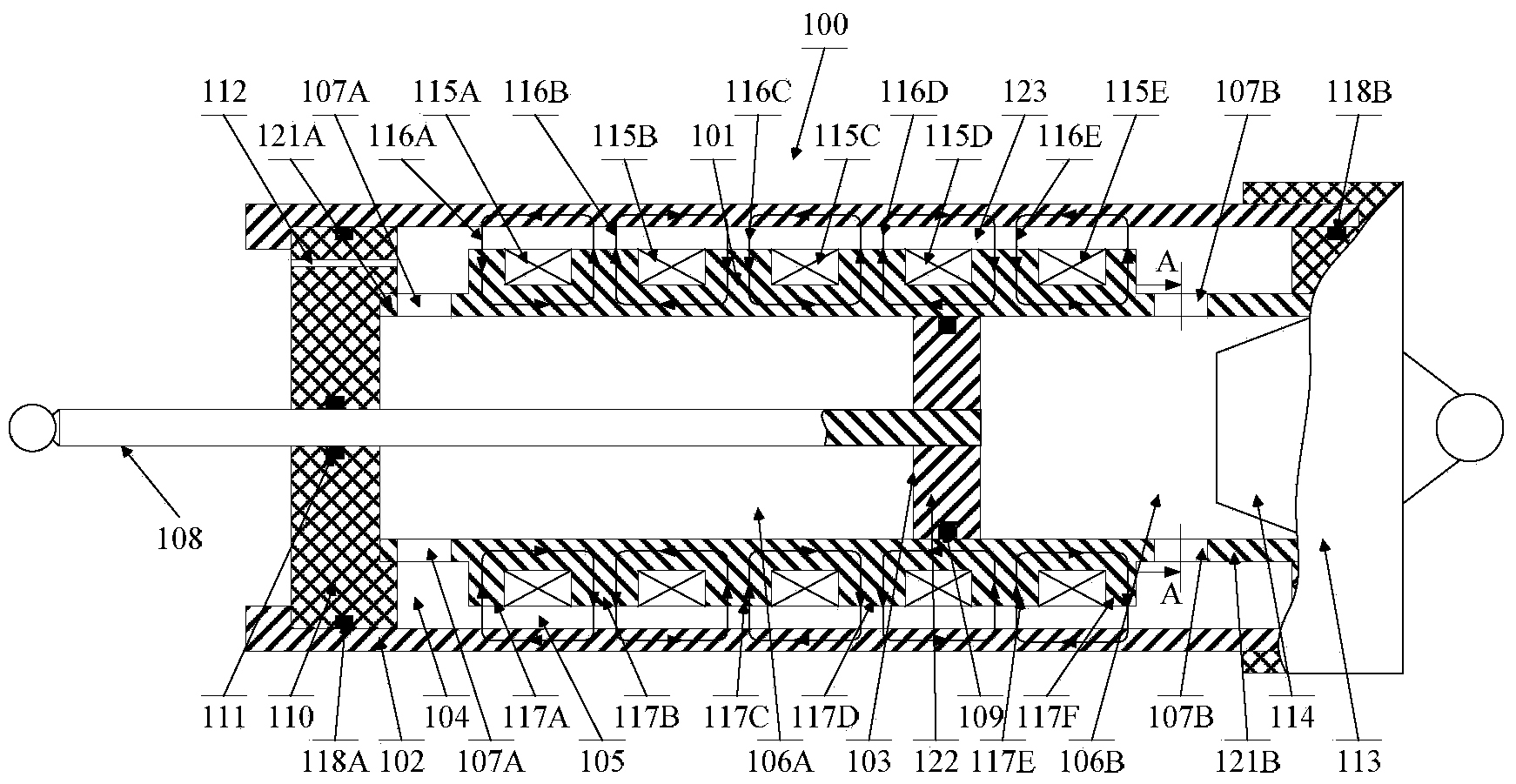
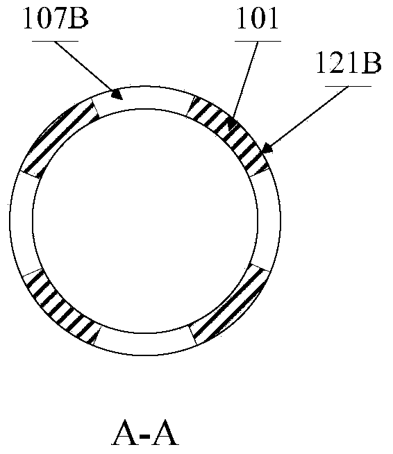
[0038] Please refer to figure 1 , is a structural cross-sectional view of the first embodiment of the magnetorheological damper suitable for high-speed impact / low-speed vibration control systems provided by the present invention, figure 2 is its A-A section view.

[0039] figure 1 The magneto-rheological damper 100 mainly includes: two concentrically installed cylinders, that is, cylinder I101 and cylinder II102 shown in the figure, a piston 103 and a magnetorheological fluid 104 .

[0040] Wherein, the cylinder I101 is installed in the cylinder II102, and an outer cavity 105 is formed between the two. The interior of the cylinder I101 is the inner cavity 106 shown in the figure. The magnetorheological fluid 104 is filled in the inner cavity 106 and the outer cavity 105 . There is at least one liquid flow hole 107A, 107B for the passage of magnetorheological fluid at both ends 121A, 121B of the cylinder I101. The magnetorheological fluid flow channel 123 formed between t...


PUM


Abstract

The invention discloses a magneto-rheological damper suitable for a high-speed impact/low-speed vibration control system. The magneto-rheological damper comprises a cylinder body I, a cylinder body II and a piston, wherein the cylinder body I comprises an inner cavity, and the piston can slide along the inner wall of the cylinder body I. The cylinder body I is arranged in the cylinder body II, and an outer cavity is formed between the cylinder body I and the cylinder body II. Magneto-rheological fluid is filled into the inner cavity and the outer cavity, and the inner cavity and the outer cavity are communicated with each other through flowing holes formed in the two ends of the cylinder body I. At least one groove where an electromagnetic coil is wound is formed in the outer wall of the cylinder body I and/or the inner wall of the cylinder body II. On the premise that the external dimension, field current and energy consumption of an existing magneto-rheological damper are not increased, the speed ratio of the movement of the piston to a magneto-rheological fluid flowing channel (the outer cavity) can be effectively lowered, and the requirements for a controllable damping ratio and a controllable speed range of the magneto-rheological damper of the high-speed impact and low-speed vibration control system can be met.

Description

technical field [0001] The invention relates to the technical field of using magnetorheological fluid for vibration reduction, in particular to a magnetorheological damper suitable for high-speed impact / low-speed vibration control systems. Background technique [0002] The magnetorheological damper is a semi-active actuator made by making full use of the characteristics of magnetorheological fluid that can change from Newtonian fluid to semi-solid or from semi-solid to Newtonian fluid in milliseconds under the action of a magnetic field. It has yield With the characteristics of large stress, fast response, low energy consumption, and stable performance, it can be applied to the landing system of aircraft / spacecraft, the rear seat buffer system of weapons and equipment such as artillery and machine guns, and the vehicle suspension and driving of amphibious (off-road) vehicles. In passenger seat suspensions and in trains, automobiles, motorcycles, bicycles, ships, buildings, s...

Claims


Application Information

Patent Timeline
IPC IPC(8): F16F9/53
Inventor 白先旭钱立军
Owner HEFEI UNIV OF TECH
Why Eureka
Try Eureka