Enhanced blind joint and metal lining ring of flaring

A technology of seamless joints and lining rings, which is applied in the direction of pipe/pipe joint/pipe fittings, engine sealing, pipeline connection arrangement, etc. The problem of being damaged by foreign objects, etc., achieves the effect of simple structure and convenient connection

Inactive Publication Date: 2014-01-22
荣京柯
View PDF11 Cites 7 Cited by
  • Summary
  • Abstract
  • Description
  • Claims
  • Application Information

AI Technical Summary

Problems solved by technology

[0008] But after experimenting for a period of time, it was found that the above-mentioned seamless joint with rubber lining still had disadvantages, such as figure 2 As shown, since the metal lining 7 is arranged on the inner side of the bell mouth 6, its outer wall has a suitable inclination to the inner wall of the bell mouth, and its positive end surface has only the width between the inner diameter of t

Method used


Image

  • Enhanced blind joint and metal lining ring of flaring
  • Enhanced blind joint and metal lining ring of flaring
  • Enhanced blind joint and metal lining ring of flaring

Examples


Embodiment Construction

[0039]The following will clearly and completely describe the technical solutions in the embodiments of the present invention with reference to the accompanying drawings in the embodiments of the present invention. Obviously, the described embodiments are only some, not all, embodiments of the present invention. Based on the embodiments of the present invention, all other embodiments obtained by persons of ordinary skill in the art without creative efforts fall within the protection scope of the present invention.

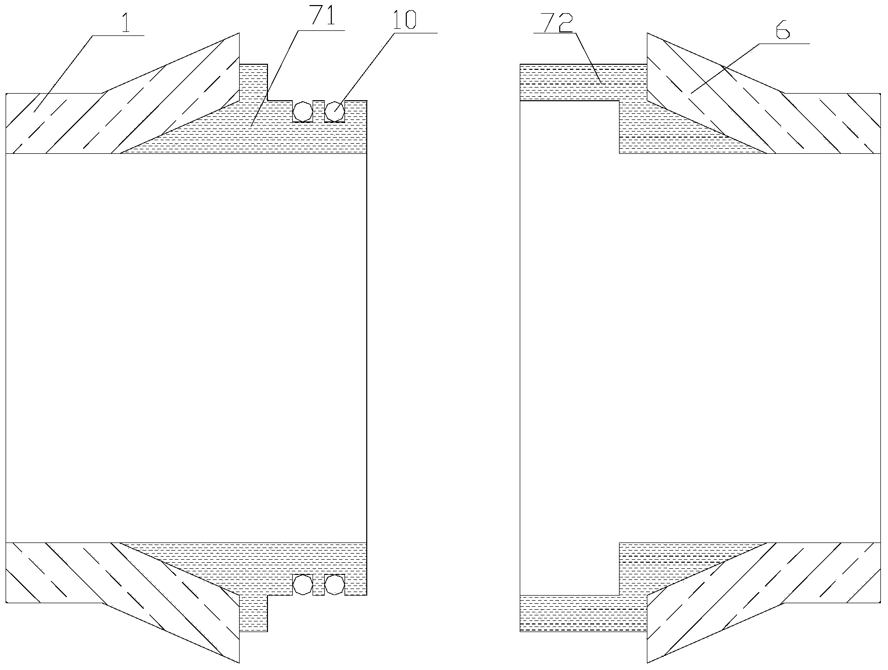
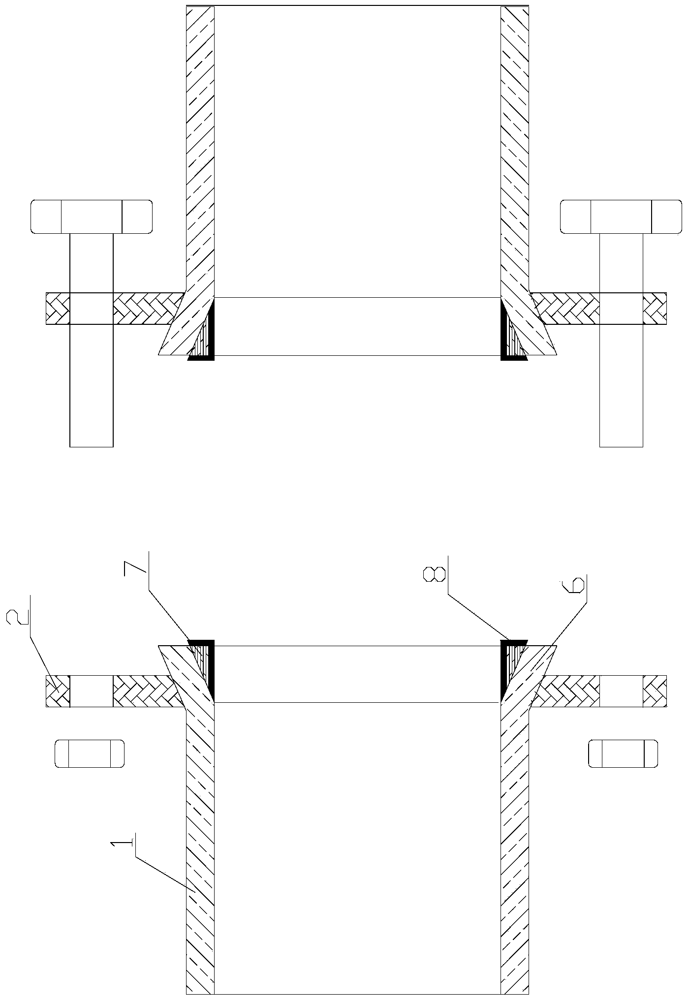
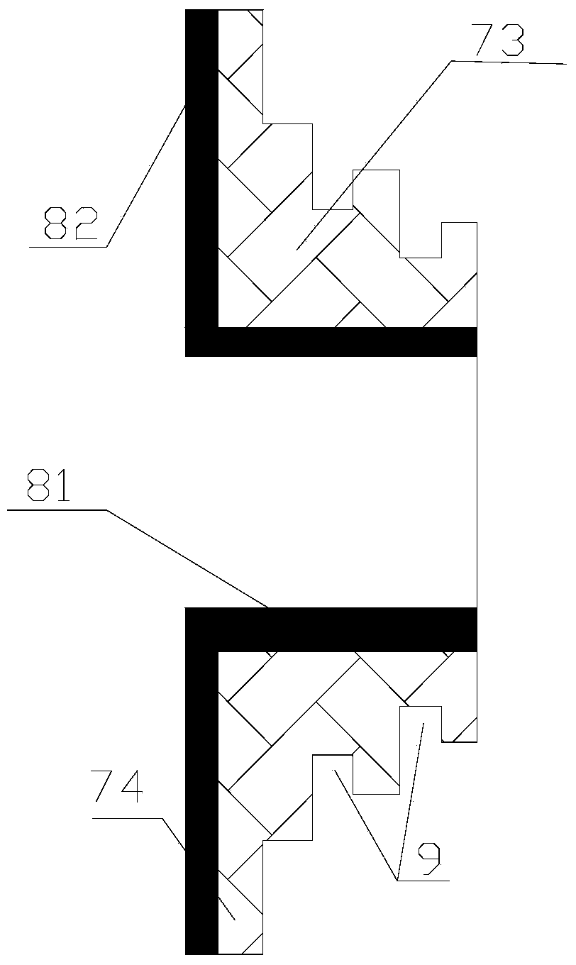
[0040] Such as Figures 3 to 6 As shown, a flaring metal gasket, its structure is: sleeved in the bell mouth of the pipe 6 (see Figure 4 to Figure 6 ) inner side and the inner part of the pipe 73 whose outer wall is adapted to the inner wall of the bell mouth 6; and the bell mouth part 74 that covers the positive end surface of the bell mouth 6 and is adapted to the positive end surface of the bell mouth 6; the inner part of the pipeline 73 and the horn The mouth ...


PUM


Abstract

The invention provides a metal lining of a flaring. The metal lining of the flaring comprises an inner pipeline part and a horn mouth part, wherein the inner pipeline part is arranged on the inner side of a horn mouth of a pipeline in a sleeved mode, the outer wall of the inner pipeline part is matched with the inner wall of the horn mouth, and the horn mouth part covers the front end face of the horn mouth and matched with the front end face of the horn mouth. The horn mouth part and the horn mouth part are of an integrally formed structure which can protect the front end face of the horn mouth against damage caused by foreign bodies. The invention further provides an enhanced blind joint of the flaring. According to a main structure of the enhanced blind joint of the flaring, the bind joint comprises two pipeline bodies respectively provided with the horn mouth, wherein a movable flange is arranged on the outer wall of each pipeline body in a sleeved mode, the inner diameter of each movable flange is smaller than the largest diameter of the corresponding horn mouth, the corresponding movable flanges of the two pipeline bodies are connected through fixing parts, and each horn mouth is provided with the metal lining ring of the flaring. The contact area between the two metal lining rings when two pipelines are connected in an abutted mode or the contact area between rubber lining layers on the metal lining rings can be increased, and therefore better sealing is achieved.

Description

technical field [0001] The invention relates to the technical field of plastic pipes or plastic composite pipes, especially the joints of plastic pipes or plastic composite pipes. Background technique [0002] The current connection methods between plastic pipes or plastic composite pipes are mostly direct welding, or connecting through movable metal flanges after welding flange roots, or connecting through movable metal flanges after direct flanging. The disadvantage is that it is difficult to repair and replace directly welded pipelines; the use environment of pipelines connected after welding with flanges is limited, and they are easy to break when floating on the water surface; the cost is high; because the welded flanges are produced by injection molding, not pipes It is produced by extrusion molding and is not resistant to wear. For the pipelines connected directly after flanging, because the flanging needs to be done by heating the nozzle, during the heating process,...

Claims


Application Information

Patent Timeline
IPC IPC(8): F16L47/14F16J15/12
CPCF16L47/14F16J15/10
Inventor 荣京柯
Owner 荣京柯
Why Eureka
Try Eureka