
Automatic detection system for fault indicators for distributing line

A fault indicator and automatic detection technology, applied in the field of detection systems, can solve the problems of inability to meet the function, performance, efficiency test, low time control accuracy, low signal output accuracy, etc., to achieve automated testing, high test efficiency, and reduced Test time and effect

Active Publication Date: 2014-01-22
STATE GRID CORP OF CHINA +1
View PDF6 Cites 21 Cited by
  • Summary
  • Abstract
  • Description
  • Claims
  • Application Information

AI Technical Summary

Problems solved by technology

However, the above-mentioned detection system is an open-loop system, which requires manual recording of the detection results and judgment, which is time-consuming and laborious, and the signal output accuracy is low, the time control accuracy is low, and the practicability is poor. It is difficult to realize automatic detection and cannot meet the requirements of "Q / GDW436 -The requirements for the function, performance and efficiency testing of fault indicators proposed in 2010 Technical Specifications for Fault Indicators of Distribution Lines

Method used


Image

  • Automatic detection system for fault indicators for distributing line
  • Automatic detection system for fault indicators for distributing line
  • Automatic detection system for fault indicators for distributing line

Examples


Embodiment Construction

[0037] The present invention will be described in further detail below in conjunction with the accompanying drawings.

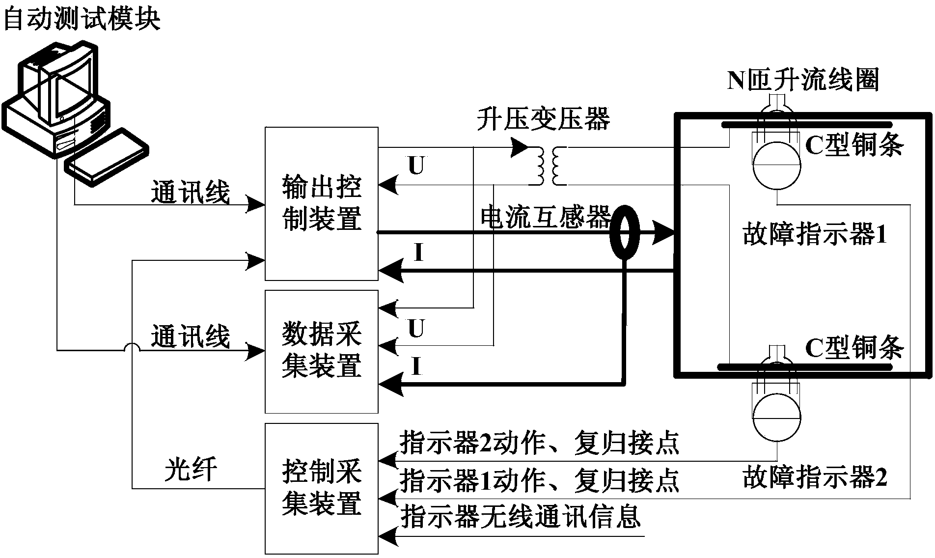
[0038] like figure 1 , the present invention provides an automatic detection system for distribution line fault indicators. ; The output control device, the data acquisition device and the control acquisition device are respectively connected to the automatic test module through computer communication lines.

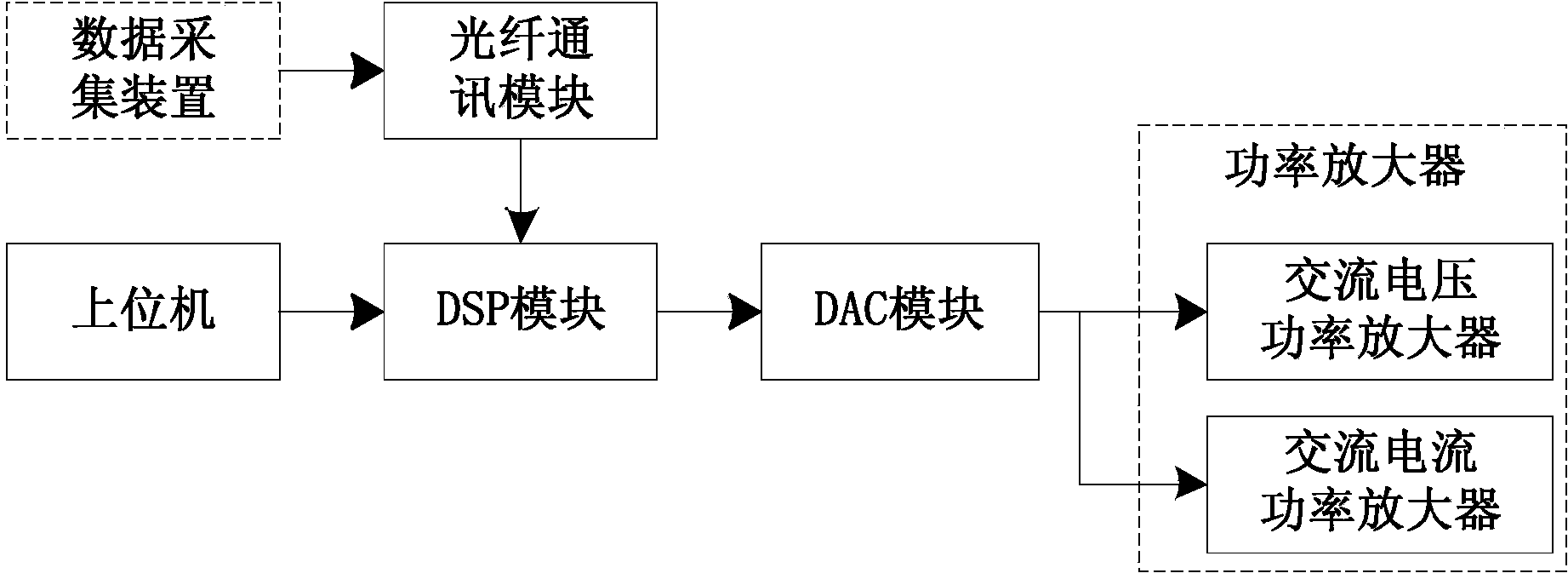
[0039] The automatic test system outputs an AC voltage signal and an AC current signal to the output control device, and the output control device outputs an AC current signal and an AC voltage signal, an AC current signal and an AC voltage signal to the step-up coil and the step-up transformer respectively The AC voltage signal of the high voltage level and the AC current signal of the high current level are respectively amplified to simulate the actual overhead line; the fault indicator is installed on the current boosting coil, and its switching nod...


PUM


Abstract

The invention provides an automatic detection system for fault indicators for a distributing line. The automatic detection system for the fault indicators for the distributing line comprises an automatic test module, an output control device, a data acquisition unit and a control acquisition unit. The output control device, the data acquisition unit and the control acquisition unit are respectively connected with the automatic test module by computer communication lines. According to the automatic detection system for the fault indicators for the distributing line provided by the invention, the real-time acquisition of the action states of the fault indicators is realized. The amplitude of a tested alternating voltage signal and the amplitude of an alternating current signal can respectively reach 10kV and 2kA, and actual signals of the line can be more accurately simulated. Moreover, the automatic detection system for the fault indicators for the distributing line is high in degree of automation, test efficiency and safety.

Description

technical field [0001] The invention relates to a detection system, in particular to an automatic detection system for a distribution line fault indicator. Background technique [0002] Although a large number of line fault indicators are used in power distribution lines, and there are a large number of manufacturers, there is no unified indicator standard and technical specification at home and abroad. They are not the same, and the technical level of the products is very different. When the line fails, the correct rate of the indicator action is low, and it is prone to false alarms and false alarms. [0003] In 2010, the State Grid Corporation promulgated the enterprise standard "Q / GDW436-2010 Technical Specifications for Distribution Line Fault Indicators", which uniformly stipulated the functions, performance indicators and test methods of fault indicators, and stipulated a variety of functions and performance test items. Although the advanced fault indicator detection...

Claims


Application Information

Patent Timeline
Patent Type & Authority Applications(China)
IPC IPC(8): G01R35/00
Inventor 李柏奎梁英邓宏芬
Owner STATE GRID CORP OF CHINA
Learn More