
Method for calculating radar cross section of corner reflector

A technology of radar cross-sectional area and calculation method, which is applied in calculation, instrument, electrical and digital data processing, etc., can solve the problems of low efficiency, cumbersome formula, low efficiency, etc., and achieves the effect of fast calculation, simple process and improved calculation efficiency

Inactive Publication Date: 2014-01-22
WUHAN UNIV
View PDF4 Cites 20 Cited by
  • Summary
  • Abstract
  • Description
  • Claims
  • Application Information

AI Technical Summary

Problems solved by technology

High-frequency approximation methods such as: ray bouncing method (SBR), Gaussian beam method (GB) and compound ray method (CR), they require a ray density of 350 / λ respectively 2 、25 / λ 2 and 4 / λ 2 , so its efficiency is low and the formula is cumbersome
The electromagnetic calculation software FEKO also uses the physical optics method (PO) to calculate the RCS after subdividing the flat plate (reflecting surface) into triangles of size λ / 8, and its efficiency is also low.

Method used

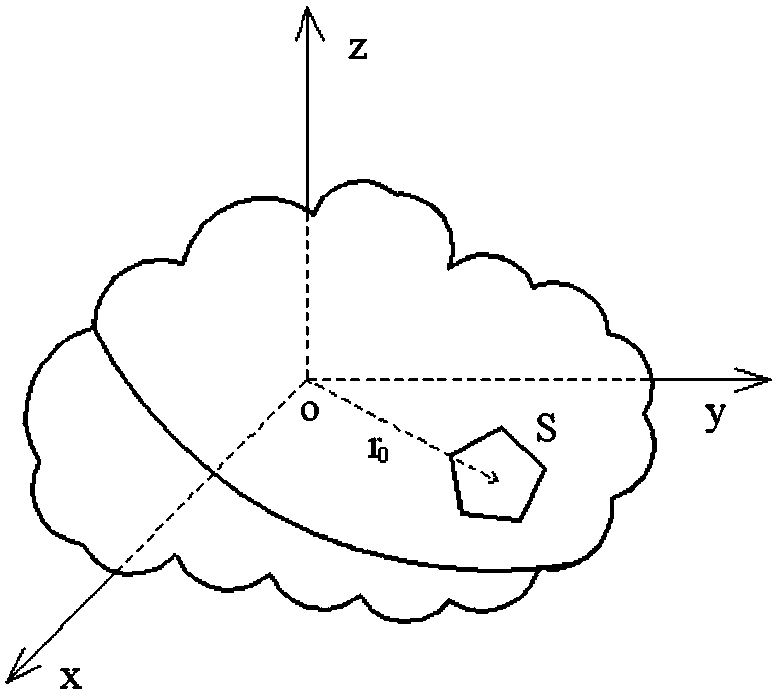
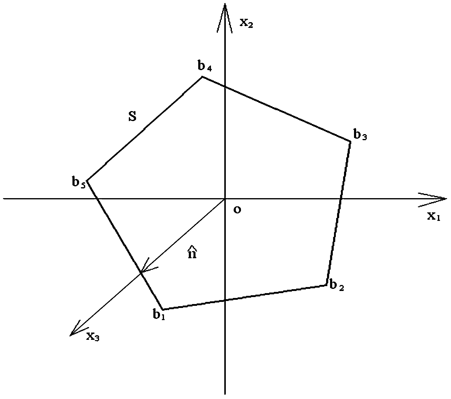

Image

  • Method for calculating radar cross section of corner reflector
  • Method for calculating radar cross section of corner reflector
  • Method for calculating radar cross section of corner reflector

Examples


Embodiment 1

[0053] The present invention will be further described below by taking a dihedral corner reflector as an example.

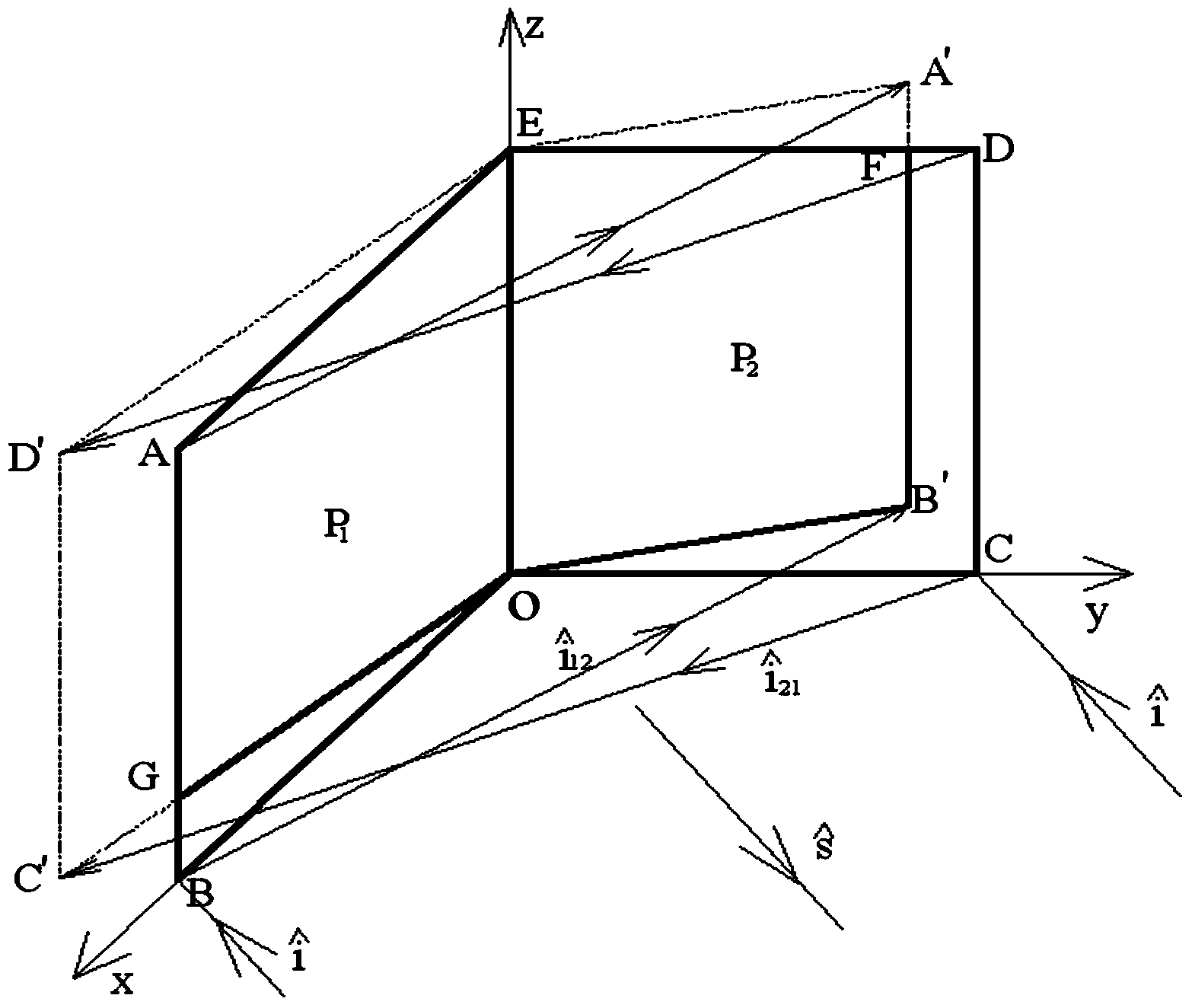
[0054] For dihedral reflectors, such as image 3 Shown, known P 1 (Quadrilateral ABOE) and P 2 (Quadrangle OCDE) All vertex coordinates of the surface, using GO to determine the lighting area:

[0055] 1)P 1 and P 2 direct wave an exposure. Using the Gordan surface element integration method to analyze the whole block P 1 ,P 2 The square root of the RCS is obtained by calculating the flat plate (quadrilateral ABOE and quadrilateral OCDE) using formula (3) and

[0056] 2)P 2 P 1 surface reflected wave of secondary irradiation. Use GO to sequentially determine P 1 Vertices (O, B, A, and E) on the plate are at P 2 Projection points O, B', A' and E on the surface, connect these points in sequence to obtain a polygon OB'A'E, and then obtain the polygon OB'A'E and P 2 Intersection of faces (polygon OB'FE). In the same way, P 1 P 2 surface reflec...

Embodiment 2

[0061] As the most commonly used triangular trihedral reflector in SAR radiation calibration, the present invention is equally applicable to calculating its RCS, and there are 15 kinds of reflection situations (P 1 ,P 2 ,P 3 ,P 1 P 2 ,P 1 P 3 ,P 2 P 3 ,P 3 P 2 ,P 3 P 1 ,P 2 P 1 ,P 1 P 2 P 3 ,P 1 P 3 P 2 ,P 2 P 1 P 3 ,P 2 P 3 P 1 ,P 3 P 1 P 2 and P 3 P 2 P 1 ), its structural dimensions are as Figure 7 As shown, OA=OB=OC=0.3m, which coincide with the x-axis, y-axis and z-axis respectively, is the scattering direction, the incident wave The angle with the z-axis is , the angle between its projection on the xoy plane and the x-axis is θ, and the frequency is 10GHz. The simulation results are shown in Figure 8, and compared with the results of the electromagnetic calculation software, Figure 8(a) shows the simulation results of this paper, Figure 8(b) shows the calculation results of the electromagnetic software, and Figure 8(c) shows the resu...


PUM


Abstract

The invention provides a method for calculating the radar cross section (RCS) of a corner reflector. RCS calculation is conducted through GO and the Gordan surface element integral method. Firstly, radial tracing is conducted on incident waves and reflected waves according to GO, so that an incident field generated every time and a corresponding lighting zone of the incident field are determined; then, a scattered field of each lighting zone is obtained through the Gordan surface element integral method and the scattered fields are accumulated, so that the total RCS is obtained. The method for calculating the RCS of the corner reflector is capable of greatly improving the calculation effect of the RCS of the corner reflector and shortening the calculation time and high in practicality.

Description

technical field [0001] The invention belongs to the technical field of synthetic aperture radar (Synthetic Aperture Radar, SAR) radiation calibration, in particular to a method for calculating the radar cross-sectional area of ​​a corner reflector. Background technique [0002] Synthetic Aperture Radar (SAR) has the advantages of all-day, all-weather, high-resolution, wide-format imaging, etc. It has been used in agriculture, hydrology, geology, forestry, ocean, cartography and mapping, military reconnaissance, target recognition and information extraction. Huge effect. Early SAR applications were mainly focused on qualitative remote sensing, that is, mainly based on the position, shape, and echo strength provided by SAR images. In terms of target recognition, the application of qualitative remote sensing has been greatly limited. In these fields, it is required to establish a quantitative relationship between radar image power and target scattering characteristics, that is...

Claims


Application Information

Patent Timeline
Patent Type & Authority Applications(China)
IPC IPC(8): G06F17/50
Inventor 李松翁寅侃杨晋陵周辉郑国兴田昕
Owner WUHAN UNIV
Learn More