Novel thin compressive overtemperature protection element structure

An over-temperature protection, thin technology, used in electrical components, emergency protection devices, circuits, etc., can solve the problems of complex structure, poor rigidity, and the insulation area is not resistant to external pressure, and achieve the effect of strong pressure resistance.

Active Publication Date: 2014-01-22
SHANGHAI CHANGYUAN WAYON CIRCUIT PROTECTION CO LTD
View PDF2 Cites 2 Cited by
  • Summary
  • Abstract
  • Description
  • Claims
  • Application Information

AI Technical Summary

Problems solved by technology

[0005] Thin thermal fuses are developing rapidly as the main over-temperature protection component of mobile phone batteries. Looking at all existing thin thermal fuse products and their patents, there are two common problems: (1) The insulation area of ​​thin thermal fuses is not resistant to external pressure, Poor rigidity; (2) Most recoverable thermal fuses are large in size and complex in structure

Method used


Image

  • Novel thin compressive overtemperature protection element structure
  • Novel thin compressive overtemperature protection element structure
  • Novel thin compressive overtemperature protection element structure

Examples


Embodiment 1

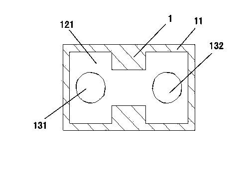
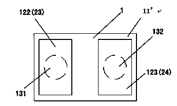
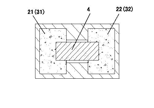
[0041] Such as figure 1 The top view of the insulation tank body of the present invention, figure 2 Bottom view of the insulation tank body of the present invention, image 3 As shown in the top view of the element structure of the present invention:

[0042] A new type of thin-type anti-pressure over-temperature protection element structure, including an insulating tank body and a metal area, and its operating temperature is set at 70 to 120 ° C, wherein:

[0043] The upper and lower surfaces of the insulating tank 1 are of symmetrical structure, with protrusions all around, and a low-lying area is formed in the middle, and two discontinuous metal areas are arranged in the low-lying area, and the upper surface is covered by a low-melting point alloy 4. The two upper left and upper right metal areas 21, 22 are connected;

[0044] A flux 5 is coated on the low melting point alloy 4;

[0045] There are left and right tin-plated layers 31, 32 on the left and right metal area...

Embodiment 2

[0058] The difference between this embodiment and Embodiment 1 is that PEI (polyetherimide) is used for the insulating tank body 1 and the insulating cover 6, and the insulating tank body 1, the low melting point alloy 4, the flux 5, and the insulating cover 7 are made according to the embodiment. 1 way to arrange and weld, finished product (50pcs) after inspection.

Embodiment 3

[0060] The difference between this embodiment and the preceding embodiments is that PA (heat-resistant polyamide) is used for the insulating tank body 1 and the insulating cover 6, and the insulating tank body 1, the low-melting point alloy 4, the flux 5, and the insulating cover 7 are made according to the embodiment. 1 way to arrange and weld, finished product (50pcs) after inspection.


PUM

PropertyMeasurementUnit
thicknessaaaaaaaaaa
thicknessaaaaaaaaaa

Abstract

The invention discloses a novel thin compressive overtemperature protection element structure which comprises an insulating slot body and a metal area, wherein the operating temperature of the structure is 70-120 DEG C; the upper surface and the lower surface of the insulating slot body are in symmetric structures, and are provided with periphery bulges; low-lying areas are formed in the middles of the upper surface and the lower surface; two discontinuous metal areas are arranged in each low-lying area; the two metal areas of the upper surface are connected by a low-melting-point alloy; the low-melting-point alloy is coated with a fluxing agent; tin coatings are arranged on the metal areas; the metal areas of the upper surface and the lower surface are communicated by blind holes of the insulating slot body; the total thickness of the tin coatings and the low-melting-point alloy coated with the fluxing agent is not greater than the depth of the low-lying areas of the insulating slot body; the upper surface of the insulating slot body is covered with an insulating layer; the insulating layer covers the tin coatings and the low-melting-point alloy coated with the fluxing agent on the insulating slot body to form a fuse; and the thickness of the fuse is less than 0.7mm. The structure is ultrathin and high in compressive capacity.

Description

technical field [0001] The invention relates to an over-temperature protection thin element structure for electronic products, in particular to a thin anti-pressure over-temperature protection element applied to a lithium-ion battery that can be charged and discharged many times. Background technique [0002] In recent years, the communication industry has developed day by day, especially in the aspect of radio communication, the market of mobile phones has been popularized to almost everyone has a mobile phone. The popularity of mobile phones has directly led to the expansion of the market for mobile phone components, especially mobile phone batteries. [0003] However, during the rapid development of the market, frequent quality problems occurred, such as mobile phone battery explosions all over the world, Nokia recalling 46 million batteries made by Panasonic, etc., making the safety of mobile phone batteries a focus. In addition, with the development of 3G (third-genera...

Claims


Application Information

Patent Timeline
Patent Type & Authority Applications(China)
IPC IPC(8): H01H37/76H01H85/05H01H85/08
Inventor 张子川钱朝勇杨彬
Owner SHANGHAI CHANGYUAN WAYON CIRCUIT PROTECTION CO LTD
Why Eureka
Try Eureka