Tri-band transmission device

A transmission device and frequency technology, applied in the field of radio frequency signal processing equipment, can solve problems such as large loss, and achieve the effect of improving transmission performance

Active Publication Date: 2016-03-23
苏州市博海元件电子科技有限公司
View PDF3 Cites 0 Cited by
  • Summary
  • Abstract
  • Description
  • Claims
  • Application Information

AI Technical Summary

Problems solved by technology

In the existing structure, the transmission of the signal of the first frequency will be affected by the upper two dielectric layers 30, 40, and the loss is relatively large

Method used


Image

  • Tri-band transmission device
  • Tri-band transmission device
  • Tri-band transmission device

Examples


Embodiment Construction

[0019] In order to describe the structure and features of the present invention in detail, the following preferred embodiments are given and described below with accompanying drawings.

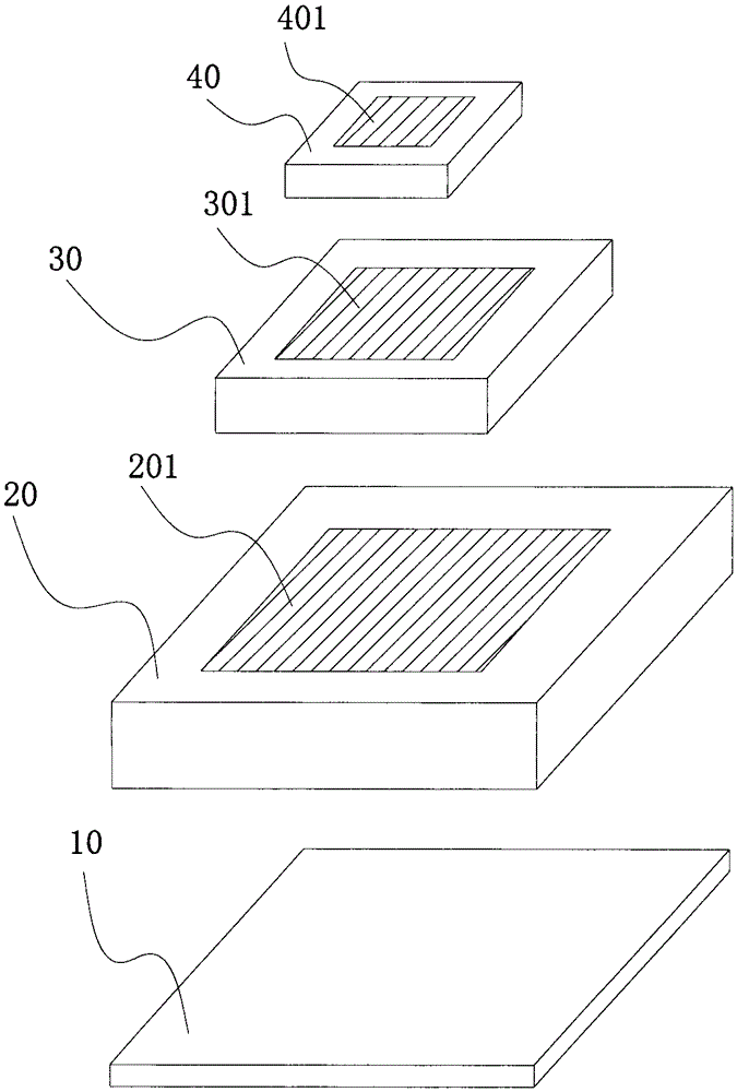
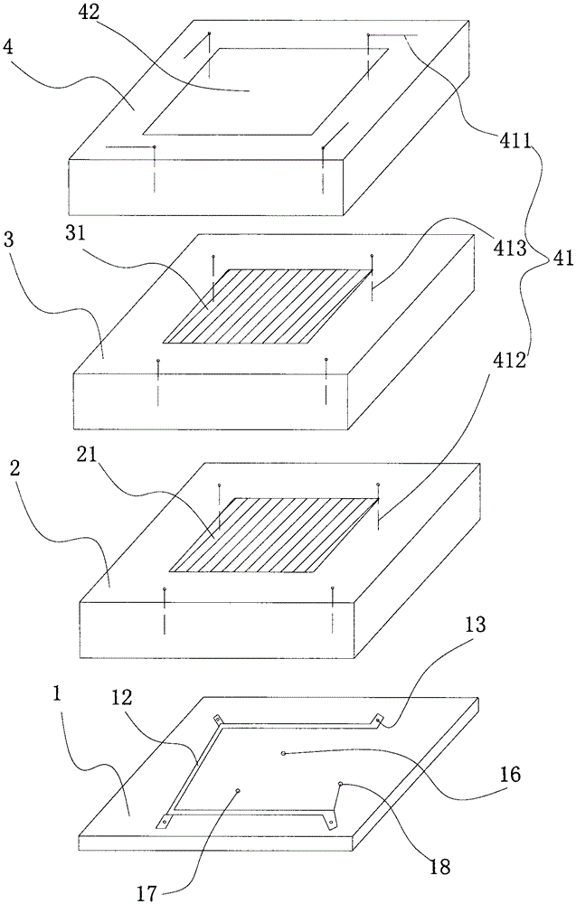
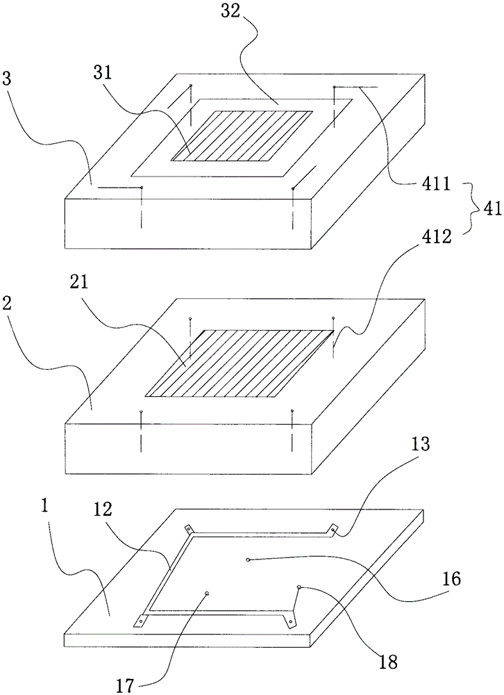
[0020] see figure 2 Embodiment 1 of the tri-frequency transmission device of the present invention generally includes: a feed layer 1 located at the bottom; a first dielectric layer 2 located above the feed layer 1, and a first metal circuit 21 is provided on the top surface; The second dielectric layer 3 above the dielectric layer 2 is provided with a second metal circuit 31 on its top surface; the third dielectric layer 4 above the second dielectric layer 2 is provided with an opening 42 penetrating up and down so that the first Two metal lines 31 are exposed; and a third metal line 41, which includes a main body 411 disposed in the third dielectric layer 4, a second extension 413 disposed in the second dielectric layer 3 and connected to the main body 411, and The first extension 412 disp...


PUM


Abstract

A three-frequency transmission device comprises a feeding layer, a first dielectric layer, a second dielectric layer and a third metallic circuit, wherein the feeding layer is arranged at the bottom, the first dielectric layer is arranged above the feeding layer and the top surface thereof is provided with a first metallic circuit, the second dielectric layer is arranged above the first dielectric layer and the top surface thereof is provided with a second metallic circuit, the third metallic circuit is arranged between the first dielectric layer and the second dielectric layer and is arranged at the outer sides of the first metallic circuit and the second metallic circuit, and the first metallic circuit, the second metallic circuit and the third metallic circuit are respectively suitable for transmission of wireless signals of three frequencies. According to the invention, the provided three-frequency transmission device enables the transmission performance of the wireless signals to be improved.

Description

technical field [0001] The present invention relates to radio frequency signal processing equipment, in particular related to the transmission of radio frequency signals. Background technique [0002] Existing triple-frequency transmission devices are generally formed by stacking three layers of dielectric and one layer of feeder. see figure 1 , which generally includes: a feed layer 10 located at the bottom; a first dielectric layer 20 located above the feed layer 10, and a first metal line 201 is provided on its top surface to form a transmission device for a first frequency, and the first frequency Relatively low, for example, for the B3 frequency band; the second dielectric layer 30 above the first dielectric layer 20 is provided with a second metal line 301 on its top surface to form a second frequency transmission device, and the second frequency is relatively Moderate, for example, it can be aimed at the L frequency band; and the third dielectric layer 40 above the ...

Claims


Application Information

Patent Timeline
Patent Type & Authority Patents(China)
IPC IPC(8): H01Q1/38H01Q1/50H01Q21/30
Inventor 王昊黄勇张霄鹏
Owner 苏州市博海元件电子科技有限公司
Why Eureka
Try Eureka