Two-way air suction type electric cable cooling device

A cooling device and air extraction technology, which is applied in the direction of cooling busbar devices, substation/switchgear cooling/ventilation, etc., can solve the problems of unfavorable cooling, suction effect needs to be improved, etc., and achieve reliable working results

Inactive Publication Date: 2014-01-22
广东天建实业有限公司
View PDF5 Cites 0 Cited by
  • Summary
  • Abstract
  • Description
  • Claims
  • Application Information

AI Technical Summary

Problems solved by technology

However, this only dissipates the heat of the specific component to other components, which is not conducive to the overall cooling
Moreover, the suction type cable cooling device in the prior art is usually provided with a suction chamber on one side of the device, and the suction effect needs to be improved.

Method used


Image

  • Two-way air suction type electric cable cooling device
  • Two-way air suction type electric cable cooling device
  • Two-way air suction type electric cable cooling device

Examples


Embodiment Construction

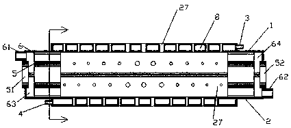
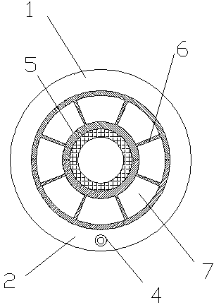
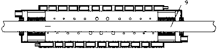
[0013] A two-way pumping type cable cooling device, comprising an upper semicircular part 1 and a lower semicircular part 2, the upper semicircular part 1 and the lower semicircular part 2 are fastened to form a cylinder, and the upper semicircular part 1 and the lower semicircular part 2 are arranged at the interface There is a sealing strip; a cylindrical coolant barrier layer is provided on the outer peripheral surface of the cylinder, and the inside of the cylinder has a cavity for accommodating the cable 9, and the cylindrical coolant barrier layer surrounds The cavity, and the liquid inlet 3 is fluidly connected to the upper right end of the cylindrical cooling liquid barrier layer, and the liquid outlet 4 is fluidly connected to the lower left end; the cylindrical cooling liquid barrier layer is also provided with Circular air hole 27, the inner circumferential sidewall of the circular air hole 27 can seal and isolate the circular air hole 27 from the inner cavity of the...


PUM


Abstract

The invention provides a two-way air suction type electric cable cooling device. The device comprises an upper semi-circle part (1) and a lower semi-circle part (2), wherein a cylindrical cooling liquid barrier layer is arranged on the outer peripheral surface of a cylinder; round air holes (27) are formed in the cylindrical cooling liquid barrier layer; two ends of both the upper semi-circle part (1) and the lower semi-circle part (2) form semi-circle bulged parts on the outer side of a radial extension partition board (6); a left air suction chamber (63) and a right air suction chamber (64) are formed in the semi-circle bulge parts respectively after the semi-circle bulge parts are fastened; one end of the left air suction chamber (63) is communicated with all partition board air channels (7) on the left side of the cylinder; and a left air suction opening (61) is communicated with the left air suction chamber at the upper part of the other end of the left air suction chamber (63).

Description

technical field [0001] The present application relates to a cooling device, in particular to a two-way suction type cable cooling device. Background technique [0002] Large-scale electrical equipment in a factory usually needs to be equipped with a large distribution box; since large-scale industrial production requires a large number of such distribution boxes, a large number of corresponding distribution boxes are usually provided in the power distribution workshop of the factory. Due to the high power consumption and power of industrial equipment, the cables supplying power to the distribution box are prone to heat accumulation under the condition of long-term high current. Especially for the cables routed inside the distribution box, due to the poor heat dissipation inside the distribution box, and the electrical components inside the distribution box are also dissipating heat, the superposition of these conditions will further aggravate the accumulation of heat . The...

Claims


Application Information

Patent Timeline
Patent Type & Authority Applications(China)
IPC IPC(8): H02G5/10H02B1/56
Inventor 范全军
Owner 广东天建实业有限公司
Why Eureka
Try Eureka